Car engine components: parts, functions, diagrams explained
Byline: Written by an independent automotive service writer with hands-on engine-bay identification experience across inline, V, and boxer layouts. I have used this same top-down, timing-side, and transmission-side method while tracing oil leaks, misfires, cooling faults, and timing-cover noise on daily drivers and higher-mileage shop vehicles. For core technical claims, I cross-check against standard references such as Internal Combustion Engine Fundamentals by John B. Heywood (McGraw-Hill), manufacturer service information, SAE technical literature, and supplier training material from companies such as Gates and Mahle.
A basic gasoline car engine usually starts with a dozen or so core parts to learn first, such as the block, head, pistons, rods, crankshaft, camshaft, valves, timing set, spark plugs, fuel injectors, intake, and exhaust. Misreading these parts can turn a small oil leak, misfire, or timing fault into major engine damage and a four-figure repair bill. I use this guide the same way I work through an unfamiliar engine bay: name the part, pin down its job, place it on the engine, then connect failure symptoms to the first checks worth making.
How to use this guide under the hood


What you can see from above versus what is hidden inside
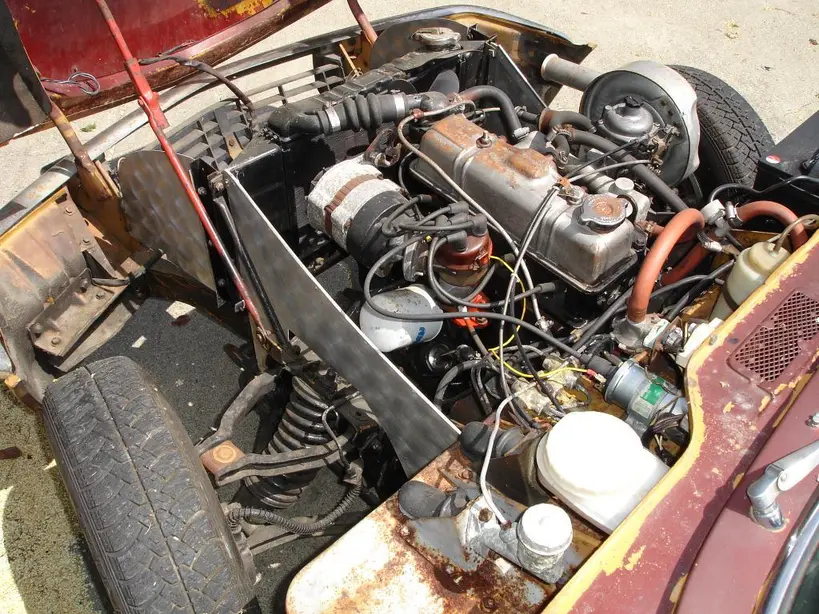
Beginners often expect every part in a car engine diagram to be visible from above. That is rarely true. The intake manifold, valve cover, ignition parts, injectors, hoses, and some sensors are often visible. Pistons, piston rings, connecting rods, the crankshaft, main bearings, and most of the flywheel are hidden inside the engine.
Typical diagrams include the engine block, combustion chamber, cylinder head, pistons, crankshaft, camshaft, timing chain, valves, and rocker arms. Real cars hide many of those parts behind covers, inside the block, or against the transmission.
How engine layout changes what part locations look like
An inline engine puts its cylinders in one row. A V engine splits them into two banks with a valley in the middle. A boxer engine lays the cylinders flat, so the heads sit out to the sides and access changes fast.
Transverse engines sit sideways in front-wheel-drive cars, so the belt or chain end may face the fender. Longitudinal engines sit front to back, so the same timing end usually faces the radiator.
The fastest way to orient yourself
- Find the top end: valve cover, ignition hardware, fuel rail, and intake pieces.
- Find the front of the engine: belts, pulleys, and often the timing cover.
- Find the bottom end: oil pan or sump under the block.
- Find the transmission side: the flywheel or flexplate sits there, mostly hidden.
- Trace hoses and wiring before guessing at a part name.
Quick diagram callout legend
Legend: A = cylinder head/top end, B = valve cover, C = intake manifold, D = exhaust manifold, E = timing cover side, F = cylinder block, G = oil pan/sump, H = crankshaft centerline, I = flywheel or flexplate side, J = water pump, K = spark plug or ignition coil area, L = fuel rail or injector area. When I identify an engine bay in person, I mentally map these same callouts before I try to diagnose a symptom.
Visible versus hidden parts by engine layout
- Inline longitudinal: usually easiest to read from above; top end, front accessory drive, and oil pan are straightforward, while pistons, rods, and crankshaft remain hidden.
- Inline transverse: top end stays visible, but the timing end may be pushed toward the fender and the exhaust side may face the firewall.
- V engine longitudinal: both heads exist, the valley can hide ignition or intake hardware, and one exhaust side may be much easier to inspect than the other.
- V engine transverse: one bank is often easy to see and the other is partly hidden by the cowl or firewall, which can make plugs, coils, and manifold access misleading.
- Boxer engine: the heads sit outward on each side, while the block center and crank area stay low and more hidden than beginners expect.
What are the main car engine components?
The main car engine components can be grouped into a few broad categories: the fixed structure, the moving internal assembly, the valve train and timing system, and the support hardware for oil, fuel, air, cooling, and ignition. Learn those groups first and diagrams make more sense, and real engines are easier to inspect without guessing.
The fixed structure
The cylinder block is the engine’s main cast body. The cylinder block, cylinder head, and crankcase form the foundation and main stationary body. In plain terms, the block is the lower main body, the head seals the top of the cylinders, and the oil pan closes the bottom.
The cylinder block contains the cylinder bores where pistons travel and oil galleries, which are drilled passages that carry oil. Cylinder block materials are usually grey cast iron or aluminum and its alloys, a standard design point described in Heywood and in manufacturer service manuals because iron offers wear resistance and stiffness while aluminum reduces mass and improves heat transfer.
The cylinder head seals the top of the cylinders. The cylinder head contains a combustion chamber above each cylinder. It also contains valve guides, valve seats, ports, coolant jackets, and threaded holes for spark plugs. Modern gasoline-engine heads are commonly aluminum alloy, while some heavy-duty applications still use cast iron; that material mix is reflected across OEM service literature and supplier references from Mahle and Federal-Mogul.
The moving assembly
Pistons take the force from combustion, slide down the cylinder bores on the power stroke, and pass that force through the wrist pin and rod to the crankshaft. Piston rings sit around the piston and seal combustion pressure while helping control oil on the cylinder wall. The connecting rod links each piston to the crankshaft.
The crankshaft takes each rod’s back-and-forth push on the crank pins and turns it into spinning output at the nose pulley and flywheel end. It is supported by main bearings, and the crankcase supports the main journals and bearing of the crankshaft. At the transmission end, the flywheel smooths rotation and stores momentum between power pulses. Those functions are basic reciprocating-engine fundamentals described in Heywood and in standard ASE training material.
The valve train and timing system
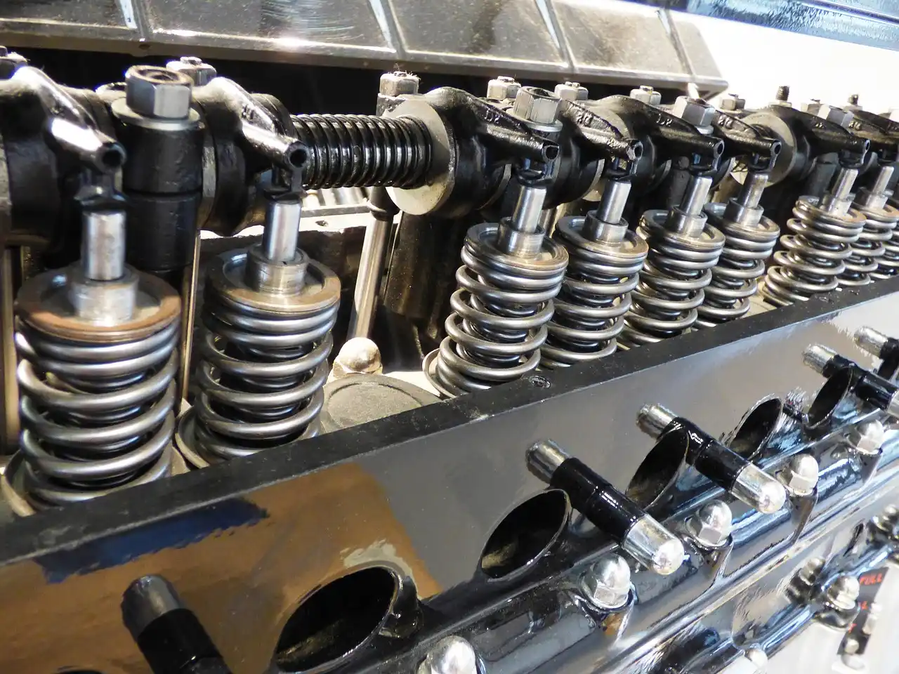
The camshaft uses egg-shaped lobes to press on lifters, followers, or rocker arms so the valves open at the right crank angle and snap shut under spring force. It is driven by a timing belt or timing chain so its rotation stays synchronized with the crankshaft. Intake valves admit fresh air or air-fuel mixture. Exhaust valves release burned gases.
If timing slips, the pistons and valves lose their planned relationship. That can cause rough running, low compression, or severe internal contact on some engines. That risk is well established in OEM service procedures and timing-belt supplier guidance from Gates and Dayco, especially on interference engines where piston-to-valve clearance is insufficient once cam timing moves far enough out of phase.
Cooling, lubrication, and attached hardware
The oil pan or sump stores the engine’s oil. The oil pan or sump is attached with a gasket to make the joint leak proof. It acts as a reservoir for storage, cooling, and ventilation of engine lubricating oil.
The water pump circulates coolant through the engine and radiator. Visible attached hardware also includes the intake manifold, exhaust manifold, spark plugs, coils, injectors, sensors, engine mounts, and front accessories. Coolant circulation, heat rejection, and pressure-lubrication architecture are all standard textbook points in SAE and OEM training references.
What engine components are shown in a car engine diagram?
A basic car engine diagram usually shows the block, head, combustion chamber, pistons, rods, crankshaft, camshaft, valves, and timing drive. What it leaves out matters just as much: many diagrams do not show the exact hose routing, sensor placement, covers, or packaging that beginners actually see under the hood.
What a beginner should expect from a diagram
A simple diagram is best used as a map of relationships, not a photo match. It shows that pistons sit in bores, rods hang from pistons, the crankshaft runs low in the block, and the camshaft controls valves up top.
What diagrams usually hide
Many diagrams do not show access or service steps. They rarely show that an inline engine may expose the exhaust manifold at the front, while a transverse V engine may hide one bank against the firewall. They also flatten the difference between visible parts and internal parts.
How can I identify engine parts under the hood?
Identify engine parts by working from large fixed pieces to smaller attached pieces: block, head, oil pan, intake, exhaust, timing side, and transmission side. Then match shape, hose routing, and symptom clues. This approach prevents common mistakes like confusing a valve cover for the head or a manifold for the block.
Practical caveat: I do not recommend touching the exhaust side, loosening fuel hardware, or opening a cooling system on a hot engine. On modern direct-injection engines, fuel pressure can be hazardous. On belt-driven accessories, loose clothing and fingers belong nowhere near a running engine. Those are simple identification rules I follow in real engine bays before diagnosis even begins.
Under-hood engine part identification table
| Component | Physical location | What it looks like | Common beginner symptom |
|---|---|---|---|
| Cylinder block | Main center body of engine, below the head and above the oil pan | Large cast metal structure with mounting points; mostly hidden by covers and manifolds | Coolant or oil seep at a freeze plug area or crack, though less common than gasket leaks |
| Cylinder head | Top of the block, under the valve cover | Upper cast section with ports for intake and exhaust; spark plugs or injectors enter here | Compression loss, coolant loss, or oil mixing when head gasket sealing fails |
| Pistons | Inside the cylinders in the block | Not visible assembled; seen only in cutaway or teardown | Knock, blow-by, or low compression when damaged |
| Piston rings | Fitted around each piston inside the cylinder | Not visible assembled; thin rings in piston grooves | Blue smoke, oil use, low compression |
| Connecting rod | Between piston and crankshaft inside the block | Not visible assembled; forged or fractured rod shape | Deep knock if bearing wear gets severe |
| Crankshaft | Low in the block, above the oil pan | Not visible assembled except pulley at front and flywheel end at rear | No-start or vibration if a crank sensor issue or severe internal damage occurs |
| Camshaft | In the head on many modern engines, sometimes in the block on older pushrod engines | Hidden by valve cover or timing cover | Misfire, poor idle, fault codes when timing or lobe wear is present |
| Timing belt or chain | Front or side of engine behind a cover | Belt is toothed rubber; chain is metal and oil-fed behind a sealed cover | Rattle, no-start, cam/crank timing codes |
| Intake valves | In the cylinder head, opening into intake ports | Hidden assembled; sit under springs or followers | Misfire or low compression if burned or sticking |
| Exhaust valves | In the cylinder head, opening into exhaust ports | Hidden assembled; aligned with exhaust passages | Tapping, misfire, or compression loss |
| Oil pan / sump | Bottom of engine | Stamped steel or cast aluminum pan with a drain plug | Oil drip on driveway or wet pan gasket seam |
| Water pump | Front or side of engine in the cooling path | Pulley-driven housing or hidden timing-cover-mounted unit on some engines | Coolant leak, bearing noise, overheating |
| Flywheel | Rear of engine where it meets the transmission | Large heavy disc with ring gear teeth; usually hidden | Starter grind or vibration on failure |
How to use the table on different layouts
On an inline engine, the table is usually easy to apply because the top, side, and bottom are clear. On a V engine, remember that the head exists on each bank. On a transverse engine, the front of the engine may point toward the fender rather than the radiator.
What beginners often mistake for an engine part
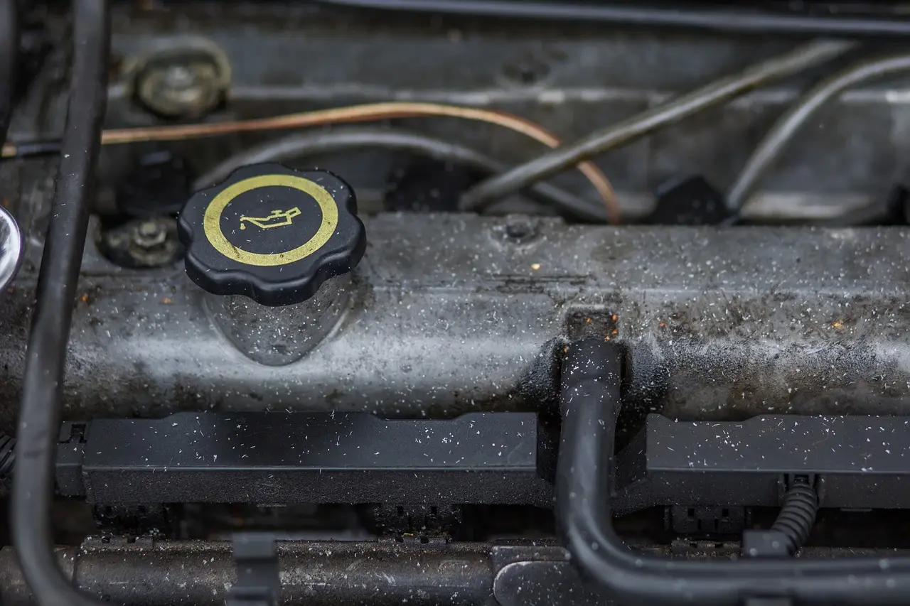
The valve cover is often mistaken for the cylinder head. The intake manifold is mistaken for the block. The plastic engine cover is mistaken for a structural part, but it is usually only cosmetic and sound-deadening.
Quick inspection checklist by symptom
- Oil smell or fresh drip: inspect valve cover perimeter, oil pan seam, front cover area, oil filter housing, and the block above any wet area before blaming the pan.
- Coolant loss or overheating: inspect water pump weep area, hose connections, thermostat housing, radiator end tanks, and signs of combustion gas in the reservoir.
- Rattle at startup: listen near the timing cover, accessory pulleys, and belt tensioner area before assuming deep internal damage.
- Misfire or rough idle: inspect coils, plugs, injector connectors, vacuum hoses, and scan data before concluding the engine has low compression.
- No-start with faster-than-normal cranking: consider a timing failure or major compression loss and avoid repeated cranking on known interference engines.
- Blue smoke: check oil level trend, PCV system condition, and signs of ring or valve-seal wear.
What does each part of a car engine do?
Each engine part has a narrow job tied to force, sealing, flow, heat, or timing. The block supports and contains, the head seals and routes gases and coolant, pistons and rods transfer combustion force, the crankshaft makes rotation, and the camshaft and valves control when the engine breathes.
Block and head
The block holds the cylinder bores, oil galleries, and lower rotating assembly. The head closes the top of the cylinders and carries the chamber, ports, valve guides, valve seats, and coolant jackets. A head gasket sits between them to seal combustion, oil, and coolant passages.
Pistons, rings, rods, and crankshaft
Pistons take pressure from combustion. Rings keep that pressure from leaking past the piston and also limit how much oil reaches the chamber. Rods transmit the force to the crankshaft, which changes that up-and-down motion into usable rotation.
Camshaft, valves, and timing drive
The camshaft is shaped to open specific valves at specific moments. The timing belt or chain synchronizes camshaft and crankshaft rotation, which keeps valve events lined up with piston position. Intake valves handle incoming charge. Exhaust valves release spent gas.
Oil pan, water pump, and flywheel
The oil pan stores oil at the bottom of the engine and gives a service point through the drain plug. The water pump circulates coolant for temperature control. The flywheel smooths engine rotation, which is why it appears in diagrams even though it is usually hidden from view.
How do pistons, valves, and the crankshaft work together?
Pistons, valves, and the crankshaft work together through timed pressure changes. The piston moves, the valves open or close to admit or release gases, and the crankshaft turns that motion into rotation. The camshaft and timing set keep those events aligned, stroke by stroke, across every cylinder.
Four-stroke cycle tied to real parts
Most modern gasoline engines use a four-stroke cycle. The intake stroke draws the air/fuel mixture into the engine through the open intake valve. The compression stroke compresses the fuel and air mixture.
The power stroke uses a spark plug to ignite the air-fuel mixture. That expanding pressure pushes the piston down and turns the crankshaft through the rod. The exhaust stroke opens the exhaust valve and forces exhaust gas to leave the cylinder. This intake-compression-power-exhaust sequence is the standard Otto-cycle description used in engineering texts such as Heywood and in manufacturer training publications.
Where the camshaft and timing drive fit in
The crankshaft reaches each piston position first. The timing belt or chain makes sure the camshaft opens and closes valves at the correct crank angle. If the belt jumps or the chain stretches, the valve events drift and the cycle stops working cleanly. Timing-belt replacement intervals and chain wear patterns are heavily documented by OEM maintenance schedules and supplier guides because loss of synchronization can produce no-starts, misfires, cam/crank correlation faults, and internal damage on interference designs.
What changes when timing or compression is off
Low compression from worn rings or valves can reduce power and make starting harder. Wrong valve timing can cause rough idle, backfiring through the intake or exhaust, and misfire symptoms or codes. In severe cases, piston-to-valve contact can bend valves. In my experience, odd cranking speed plus a sudden no-start is one of the fastest clues that the timing relationship may have failed.
What is the difference between the cylinder block and cylinder head?
The cylinder block is the lower main structure that contains the bores, oil passages, and lower rotating parts, while the cylinder head seals the top of the cylinders and manages combustion chamber shape, ports, valves, and coolant flow. They bolt together with a head gasket between them.
What lives in the block
The block houses the cylinders, pistons, rings, connecting rods, and crankshaft. It also carries the lower coolant and oil passages and provides mounting points for accessories, brackets, and the oil pan.
What lives in the head
The head contains the combustion chamber above each cylinder, along with valve guides, valve seats, ports, coolant jackets, and threaded holes for spark plugs. On many engines, the camshaft also lives in the head under the valve cover.
How the head gasket joins them and what happens when it fails
The head gasket seals combustion pressure, oil passages, and coolant passages between the block and head. When it fails, beginners may notice overheating, white exhaust smoke, bubbles in the coolant reservoir, oil contamination, or low compression in one or more cylinders. Those symptoms are widely recognized in OEM diagnostic charts and ASE-style cooling-system and cylinder-sealing tests.
Which engine parts are inside the combustion chamber?
The combustion chamber is shaped by the cylinder head, the top of the piston, and the area around the valves and spark plug or injector. Beginners should think of it as a shared space formed by several parts rather than a single separate component hidden in the head.
Chamber shape, piston crown, and valve area
The chamber is partly in the head and partly at the piston top when the piston reaches the top of its travel. Intake and exhaust valves open into that space. The piston crown, meaning the piston top, also affects mixture motion and compression.
Gasoline versus diesel chamber differences
Gasoline engines usually place a spark plug in the head. Diesel engines usually place a fuel injector there instead and rely on compression ignition rather than a spark. Under the hood, diesel engines often show heavier fuel lines, a high-pressure fuel system, and no ignition coils.
How direct injection changes the hardware around the chamber
With direct injection, the injector sprays straight into the combustion chamber instead of into the intake port. That adds a high-pressure pump, fuel rail, and different injector placement near the head. It also changes carbon buildup patterns because intake valves no longer get washed by fuel. That intake-valve deposit tendency is well documented in OEM service bulletins and SAE papers on GDI deposit formation.
How does a four-stroke engine cycle work?
A four-stroke engine cycle works by repeating intake, compression, power, and exhaust in each cylinder. The piston changes position every stroke, the valves open only when needed, and the crankshaft carries the cycle forward. Watching the cycle this way makes diagrams and failure symptoms easier to connect.
Stroke-by-stroke view
On intake, the piston moves down while the intake valve is open. On compression, the piston rises with both valves closed. On power, combustion pushes the piston down. On exhaust, the piston rises again while the exhaust valve opens.
Why the cycle matters during diagnosis
A misfire under load can point to ignition, injection, compression, or valve timing faults. A steady loss of compression suggests ring or valve sealing trouble. A no-start with odd cranking speed can point to a timing set failure that has disrupted the cycle. Compression, leak-down, and cam/crank correlation checks are the standard next steps in service information when these symptoms appear.
What parts are usually attached to the engine block?
Parts attached to the engine block usually include the cylinder head, oil pan, timing cover, water pump, engine mounts, accessory brackets, intake and exhaust hardware, sensors, and the transmission interface. The exact layout changes by engine family, but those attachment zones stay fairly consistent.
Timing cover side, accessory side, and transmission side
The timing cover side often contains the belt or chain drive, front crank pulley, and sometimes the water pump. The accessory side carries the alternator, power steering pump, and air-conditioning compressor brackets. The transmission side carries the flywheel or flexplate and starter engagement area.
Cooling and lubrication attachments
The oil pan bolts to the bottom of the block with a gasket. The oil filter mount may sit on the block or a housing nearby. Coolant passages connect the block to the head, water pump, thermostat housing, and radiator hoses.
Sensors, mounts, and modern control hardware
Modern engines add crank and cam sensors, knock sensors, oil pressure sensors, and coolant temperature sensors. Variable valve timing hardware often sits at the camshaft ends under the timing cover or near the top front of the head. Engine mounts also bolt to block or bracket locations that beginners can trace visually.
Which engine components wear out or fail first?
The parts that usually fail first are external seals, timing components, water pumps, plastic cooling pieces, ignition parts on gasoline engines, and sensors. Internal hard parts like the block or crankshaft often last much longer, so diagnosis should start with accessible failures before assuming major internal damage.
Common early failures and what they look like
Valve cover and oil pan leaks are common because gaskets age and harden. Water pumps often fail by leaking from the shaft seal or making bearing noise. Timing belts age with time and heat, while chains can stretch or rattle when guides and tensioners wear.
Sensors can fail with no visible damage. A bad cam or crank sensor may cause hard starting or stalling. Ignition coils, spark plugs, and injectors can also cause misfires that mimic mechanical problems. Common symptom patterns such as chain rattle, cam/crank correlation codes, blue smoke from oil control issues, or overheating from pump leakage are all consistent with OEM diagnostics and supplier technical bulletins.
Repair priority, labor difficulty, and rough cost impact
Timing components rank high because failure can stop the engine instantly and can cause valve damage on some designs. Water pump access ranges from easy external service to deep timing-cover work. Head gasket jobs are usually labor-heavy because the top end must come apart in order.
Oil leaks from a valve cover are usually lower priority than coolant loss, overheating, or timing noise. A leaking oil pan can be simple on one car and awkward on another if a crossmember blocks removal. Sensor replacement is often easier than internal mechanical work, but diagnosis matters before parts are replaced.
How oil and water pump failures differ
A failing oil pump triggers low oil pressure warnings, lifter noise, or bearing knock, while a bad water pump causes overheating, coolant loss, or a whirring leak. Confusing the two symptoms can destroy an engine in minutes because each pump protects a completely different system.
Understanding these distinct warning signs lets you diagnose the exact problem before guessing. The comparison of oil vs water pumps breaks down what each component does, which dashboard lights to trust, and the specific damage path that follows when either one fails. Matching the symptom to the correct pump ensures you shut the engine down at the right time and avoid catastrophic internal damage.
How modern engines change the old diagram
Variable valve timing hardware and where it sits
Older textbook diagrams show a fixed camshaft and simple valve timing. Many modern engines add variable valve timing hardware at the camshaft ends. These phasers alter cam position while running, which changes when the valves open and close. When they stick or lose oil control, idle quality and fault codes often follow.
Direct injection pumps, rails, and injectors in real layouts
Port injection places injectors in the intake path. Direct injection moves them into the head, near the chamber, and adds a high-pressure pump driven by the engine. Under the hood, that means more metal fuel hardware around the top and side of the engine than old diagrams usually show.
Why sensors and actuators now matter when identifying engine parts
Beginners often focus only on metal hard parts. On modern engines, electrical pieces matter almost as much during diagnosis. Cam sensors, crank sensors, coolant sensors, oil control solenoids, throttle actuators, and manifold pressure sensors all affect how the classic parts do their jobs.
Frequently asked questions
What are the main car engine components?
The main components are the block, head, pistons, rings, connecting rods, crankshaft, camshaft, valves, timing belt or chain, oil pan, water pump, and flywheel, plus attached systems like intake, exhaust, ignition, and fuel delivery. Learning structure first helps a beginner place every smaller part around it.
What does each part of a car engine do?
The block supports the engine, the head seals the cylinders and holds the chamber and valves, pistons and rods transfer combustion force, the crankshaft makes rotation, the camshaft and valves control gas flow, the timing set synchronizes movement, and the oil pan and water pump support lubrication and cooling.
How do pistons, valves, and the crankshaft work together?
Pistons move inside the cylinders, valves open and close to control gas flow, and the crankshaft turns piston motion into rotation. The camshaft and timing set keep valve movement aligned with piston position so the four strokes happen in the correct order and the engine produces usable power.
What is the difference between the cylinder block and cylinder head?
The cylinder block is the lower main structure with the bores and lower rotating assembly, while the cylinder head bolts on top and contains the combustion chamber, ports, valves, and much of the cooling path. A head gasket between them seals combustion, oil, and coolant passages.
Which engine components wear out or fail first?
External gaskets, timing components, water pumps, sensors, spark plugs, coils, and some plastic cooling parts often fail before core hard parts like the block or crankshaft. Beginners should inspect leaks, noises, overheating, and misfire symptoms first because those problems often start at accessible components.
How can I identify engine parts under the hood?
Start by locating the top end, timing side, oil pan, and transmission side. Then separate visible parts from hidden internal parts. Use shape, hose routing, wiring, and symptom clues, and remember that covers, manifolds, and brackets can hide the actual block, head, and timing hardware underneath.
What engine components are shown in a car engine diagram?
A basic engine diagram usually shows the block, head, pistons, rods, crankshaft, camshaft, valves, and timing drive because those are the core relationships that explain how the engine works. It usually does not show packaging details such as covers, hose routing, wiring, or the exact access issues you face under the hood.
Which engine parts are inside the combustion chamber?
The combustion chamber includes the space shaped by the cylinder head, piston crown, valve area, and spark plug or injector location. In other words, the chamber is not one separate bolt-on part; it is the working space formed by several parts at the top of the cylinder.
How does a four-stroke engine cycle work?
A four-stroke engine repeats intake, compression, power, and exhaust. The piston moves through each stroke, the valves open only when needed, and the crankshaft turns those pressure events into rotating output. This cycle is the basis for understanding misfires, low compression, and timing-related no-starts.
What parts are usually attached to the engine block?
The block usually carries the head on top, the oil pan below, the timing cover at the front or side, engine mounts, accessory brackets, sensors, and the transmission interface at the rear. Depending on the design, the water pump, filter mount, and some cooling hardware may also attach directly to the block.
What are common symptoms of timing failure?
Common timing-failure symptoms include rattling from the timing cover area, cam/crank correlation fault codes, rough running, sudden no-start, unusually fast cranking from lost compression, and in severe cases internal contact noise. On interference engines, repeated cranking after a major timing failure can increase valve damage, so diagnosis should come before more start attempts.
Sources
- Heywood, John B. Internal Combustion Engine Fundamentals. McGraw-Hill.
- Gates technical training and timing-belt replacement guidance.
- Dayco technical bulletins on timing-belt and timing-chain service symptoms.
- Mahle and Federal-Mogul technical material on piston, ring, and cylinder-head construction.
- ASE training standards for engine repair and engine performance diagnostics.
- OEM factory service information and maintenance schedules for timing-system inspection, cam/crank correlation diagnostics, cooling-system diagnosis, and compression testing.
- SAE technical literature on gasoline direct injection, valve deposits, lubrication, and cooling-system operation.
Products related to this article
Sponsored / affiliate links. As an Amazon Associate I earn from qualifying purchases. I may earn additional commission from eligible campaigns.