How to Diagnose a Bad Crankshaft Sensor vs Camshaft Sensor
Use a scan tool and start behavior to split the fault: no RPM signal during cranking points to the crankshaft sensor, while a stored cam/crank correlation code with RPM present more often points to the camshaft sensor. Mixing them up can lead to repeat no-starts, wasted parts, and missed wiring or timing faults. This guide gives a symptom-by-symptom decision tree, scan data checks, and safe signal tests to identify the bad sensor before you replace anything.
This guide is part of our Car engine components: parts, functions and diagrams series.
| Decision factor | How to Diagnose a Bad Crankshaft Sensor | Camshaft Sensor | Winner |
|---|---|---|---|
| Primary job | Measures crankshaft speed and position for ECU timing decisions | Reports cam position so the ECU can confirm valve timing and sync | Tie |
| Typical failure clue | No RPM during cranking, stall, or no-start | RPM may still show, but sync or correlation faults appear | Crankshaft sensor |
| First-pass diagnosis | Check stored codes, live RPM, connector, then sensor output | Check correlation codes, live sync status, then waveform quality | Tie |
| Safe simple test | Resistance on confirmed inductive sensor; power and signal on Hall type | Power, ground, and waveform checks are usually needed | Crankshaft sensor |
| Common confusion | Bad wiring or damaged ring gear can mimic a failed sensor | Cam code may appear when crank signal or sync is the real fault | Tie |
What you’ll need
- OBD scan tool with live data and fault memory access
- Digital multimeter
- Oscilloscope, if available
- Basic hand tools
- Wiring diagram or service data for the vehicle
- Contact cleaner
- Inspection light
How to tell crankshaft and camshaft sensor faults apart
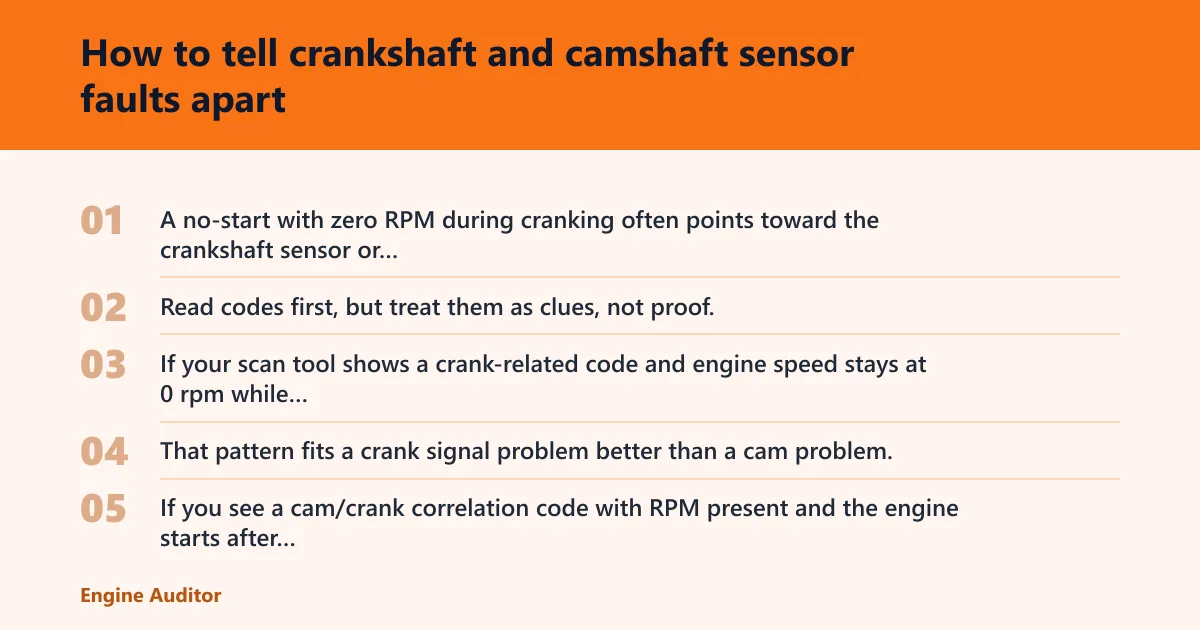
Start with the symptom pattern. A no-start with zero RPM during cranking often points toward the crankshaft sensor or its circuit, while a rough run with a valid RPM signal but lost sync may lean toward the camshaft sensor, correlation, or timing-related faults. Read codes first, but treat them as clues, not proof.
If your scan tool shows a crank-related code and engine speed stays at 0 rpm while cranking, that may fit a crank signal problem better than a cam problem. That pattern fits a crank signal problem better than a cam problem. If you see a cam/crank correlation code with RPM present and the engine starts after extended cranking, that may point more toward cam/crank relationship or timing data than a dead crank sensor alone.
How do the two sensors differ in engine control?
The crankshaft position sensor measures crankshaft speed and position, often near the flywheel ring gear. The ECU uses that signal for injection and ignition timing. The camshaft sensor tells the ECU where the camshaft is, so it can confirm cylinder phase and sync the injection event.
That difference matters during diagnosis. A missing crank signal usually blocks basic engine operation. A missing cam signal may still allow the engine to run on fallback logic, then set a code or run poorly once the ECU loses sync confidence.
What symptoms does a bad crankshaft sensor cause?
A bad crankshaft sensor can cause stalling, no-start, and stored fault codes. In many cases the engine will crank normally but the scan tool will show no engine speed while the starter turns the engine. Intermittent failures can also produce sudden cut-out and restart-after-cooldown behavior.
Common causes include internal short circuits, breaks in wiring, mechanical damage to the encoder wheel, soiling from metal abrasion, and incorrect air gap. Those issues can interrupt the signal even when the sensor itself is not fully dead.
What symptoms does a bad camshaft sensor cause?
A bad camshaft sensor often shows up as rough idle, extended crank, hard starting, or a correlation code rather than a total no-start. The engine control unit still may receive crank speed data, so RPM can remain present while sync status drops out. That is the key clue.
Camshaft faults are easy to confuse with crankshaft faults because both can cause poor starting and drivability complaints. The difference is that cam faults more often disturb sync and timing confirmation than the basic RPM signal.
What tools do you need to diagnose crankshaft versus camshaft sensor problems?
Use a scan tool that shows live RPM, cam/crank sync status, and stored as well as pending codes first. A digital multimeter helps on confirmed inductive sensors, plus supply, ground, and continuity checks on the wiring. An oscilloscope is the best tool for confirming a clean crank or cam waveform, especially when the fault is intermittent.
Also keep a wiring diagram, contact cleaner, and basic hand tools nearby. If the sensor is near a flywheel ring gear or encoder wheel, inspection light access matters because contamination, damaged teeth, or poor fitment can create a false sensor fault.
What should I check before replacing the sensor?
Check the connector, wire loom, and target hardware before replacing any part. Inspect pin tension, corrosion, oil intrusion, and connector fitment. Then inspect the wire loom for rub-through, breaks, and any short-to-ground point. Mechanical damage to the reluctor, encoder wheel, or ring gear can mimic a dead sensor.
Also verify sensor-to-target distance. If the gap is wrong, signal quality drops even when the sensor tests “good” on the bench. The ECU only needs one weak or corrupted pulse to lose timing confidence.
Step 1: Read the fault memory and live data
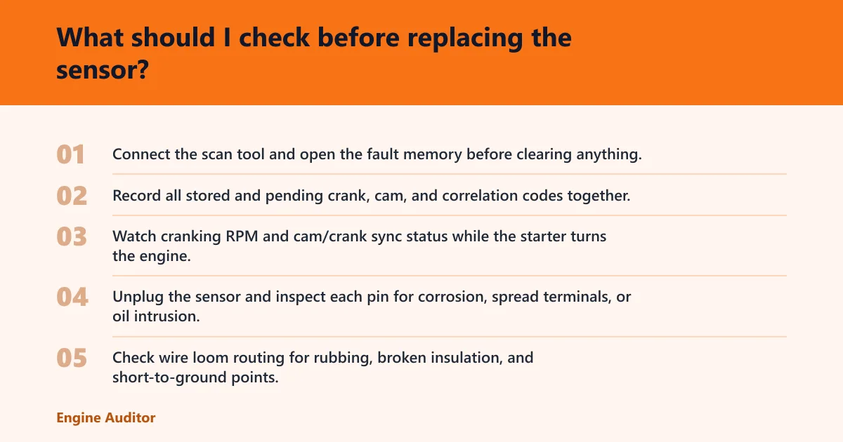
- Connect the scan tool and open the fault memory before clearing anything.
- Record all stored and pending crank, cam, and correlation codes together.
- Watch cranking RPM and cam/crank sync status while the starter turns the engine.
If RPM stays at zero during cranking, focus on the crank sensor circuit first. If RPM is present but sync drops out, move toward cam sensor or correlation checks.
Step 2: Inspect the sensor, connector, and harness
- Unplug the sensor and inspect each pin for corrosion, spread terminals, or oil intrusion.
- Check wire loom routing for rubbing, broken insulation, and short-to-ground points.
- Verify the sensor is seated correctly and that the target gap matches service data.
Connector fit matters. A loose terminal can create an intermittent stall that looks like a dead sensor. Metal debris near the tip can also distort the signal, especially on magnetic designs.
Step 3: Confirm the sensor type before testing
- Use the wiring diagram or service data to identify inductive or Hall-effect construction.
- Look at the connector count only as a clue; do not assume type from pin count alone.
- Use resistance checks only on a confirmed inductive sensor.
If the sensor has a 2-pin connector, it is most likely inductive. Inductive sensor internal resistance should be 200 to 1,000 ohms. A Hall generator should be checked for square-wave signal and supply voltage, not measured blindly with an ohmmeter if its type is unconfirmed.
Step 4: Test the signal the safe way
- On a confirmed inductive sensor, measure resistance and compare it to service data.
- On a Hall sensor, check the supply voltage, ground, and square-wave output.
- Use an oscilloscope to compare signal consistency across cranking and idle.
Waveform strength and consistency matter more than the visual shape alone. A weak or noisy trace can point to wiring, contamination, or air-gap problems even when the sensor outputs something that looks normal at first glance.
Can a crankshaft sensor code be confused with a camshaft sensor code?
Yes. OBD fault codes may point to one sensor while the root cause sits in the other sensor’s circuit, the shared wiring, or the mechanical target. That is why code reading must be paired with live RPM data, sync status, and connector checks before parts replacement.
Correlation faults are the classic trap. If the ECU loses agreement between crank and cam signals, it may store a code that looks like a cam problem even when the crank signal is distorted, intermittent, or delayed.
Crank vs cam diagnostic matrix
| Decision factor | Crankshaft sensor fault | Camshaft sensor fault | Winner |
|---|---|---|---|
| Start behavior | No-start or start-then-stall is common | Extended crank, rough start, or fallback run is common | Crankshaft sensor |
| RPM during cranking | Often zero or erratic | Usually present | Crankshaft sensor |
| Common code pattern | Crank sensor circuit codes, sometimes correlation codes | Cam sensor circuit or correlation codes | Tie |
| Connector count clue | Often 2-pin on inductive types; Hall types vary | Often 3-pin on Hall types; construction still must be confirmed | Tie |
| Expected waveform | Sinus signal on inductive sensors; square-wave on Hall sensors | Square-wave output is common on Hall sensors | Tie |
| First-pass test | Read RPM, inspect wiring, then test sensor output | Read sync status, inspect wiring, then test sensor output | Tie |
Why the matrix favors the crank sensor for no-start
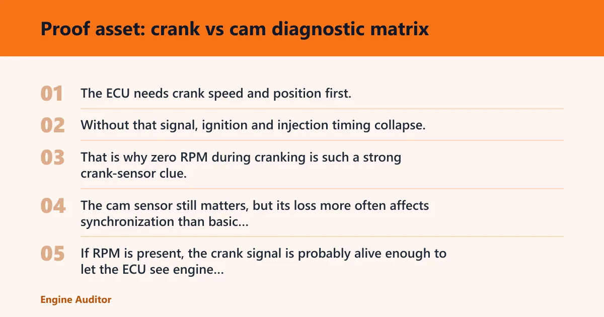
The ECU needs crank speed and position first. Without that signal, ignition and injection timing collapse, so the engine may not start at all. That is why zero RPM during cranking is such a strong crank-sensor clue.
The cam sensor still matters, but its loss more often affects synchronization than basic engine rotation awareness. If RPM is present, the crank signal is probably alive enough to let the ECU see engine speed.
Why cam faults often look like correlation faults
The camshaft sensor is used for timing and synchronization with the crank signal. If its waveform is wrong, delayed, or missing, the ECU may flag a cam/crank correlation code rather than a simple “cam sensor failed” message.
That is why code patterns alone are not enough. A damaged reluctor tooth, poor sensor gap, or wiring break can make the ECU think the cam and crank are out of agreement.
Why waveform checks beat guesswork
An oscilloscope can show whether the signal is stable during cranking and running. For inductive sensors, look for a sinus signal. For Hall sensors, look for a square-wave signal with solid amplitude and repeatable edges.
Appearance matters less than consistency. A signal that drops out, jitters, or flattens during heat soak or cranking is more useful than a waveform that simply looks “busy.”
Can a bad crankshaft sensor make the engine stall or not start?
Yes. A faulty crankshaft sensor can cause the engine to stall or produce a no-start condition because the ECU loses the speed and position data it needs for fuel and spark timing. A stored fault code may follow, but the symptom often appears before the code is confirmed.
If the engine stalls suddenly and then restarts after a cool-down period, inspect the connector, wire loom, and target wheel before replacing the sensor. Heat-related opens and internal shorts are common failure paths.
Where is the crankshaft sensor usually located?
The crankshaft position sensor is commonly installed near the flywheel ring gear. On some engines it reads teeth on the crankshaft reluctor or encoder wheel, so access may be low on the block, near the transmission bellhousing, or close to the front pulley area.
Location alone does not prove the diagnosis. A sensor mounted low on the engine is more exposed to heat, oil, and metal debris, which makes a visual check even more important.
Common mistakes
Replacing the crank sensor because the engine stalled once is a weak move. Read the fault memory first, then confirm RPM, wiring, and target condition. A momentary stall can come from a bad connector or a damaged ring gear as easily as from the sensor itself.
Another mistake is using an ohmmeter on an unconfirmed Hall sensor. If the sensor is not verified as inductive, use supply voltage, ground, and signal checks instead. Also avoid skipping the mechanical checks on the reluctor, encoder wheel, or ring gear.
Choose the crankshaft sensor path if the symptom is no RPM during cranking
Pick the crankshaft path when the engine cranks, but the scan tool shows no RPM or wildly unstable RPM. That is the stronger match for crank sensor, connector, wiring, or target-wheel failure. Start there, then confirm with safe signal testing before replacing anything.
Consider the camshaft path when RPM is present, the engine may start after a long crank, and the main clue is a sync or correlation code. If both sensors or both circuits look questionable, fix the wiring or mechanical target issue first, because the ECU depends on both signals for correct timing.
Frequently asked questions
How do I tell if my crankshaft sensor is bad or my camshaft sensor?
Check cranking RPM first. No RPM points toward the crankshaft sensor, while RPM present with lost sync or a correlation code points more toward the camshaft sensor. Then inspect the connector, wire loom, and target wheel before changing parts.
What symptoms does a bad crankshaft sensor cause?
Common symptoms include stalling, no-start, and stored fault codes. A scanner may show zero or erratic RPM while the engine is cranking. Mechanical damage, contamination, or wiring faults can create the same symptom pattern.
What symptoms does a bad camshaft sensor cause?
Camshaft sensor faults often show up as extended crank, rough running, or correlation codes rather than a hard no-start. If the crank signal is still present, the ECU may keep running but lose sync confidence. That difference helps separate the two faults.
Can a crankshaft sensor code be confused with a camshaft sensor code?
Yes. Correlation faults, shared wiring damage, or a bad target wheel can make the ECU store the wrong-looking code. Use live RPM, sync data, and waveform testing before deciding which sensor failed.
How do I test a crankshaft position sensor with a multimeter?
Use resistance mode only on a confirmed inductive sensor. If service data lists a resistance range, compare the reading to that specification. For Hall sensors, check supply voltage and ground instead; do not rely on resistance alone if the sensor type is unconfirmed.
How do I test a Hall sensor without damaging it?
Back-probe the connector and verify supply voltage, ground, and square-wave output with a meter or oscilloscope. Do not use an ohmmeter on an unconfirmed Hall sensor. If the waveform is missing, inspect wiring and connector fit before replacing the part.
Products related to this article
Sponsored / affiliate links. As an Amazon Associate I earn from qualifying purchases. I may earn additional commission from eligible campaigns.
 ENA Engine Crankshaft Position Sensor Compatible with Chrysler Mercedes-Benz Dodge Freightliner Maybach Crossfire Sprinter 2500/3500 57 62 B200 C230 C240 C280 C32 AMG C320 2002-2014 Replaces PC497
 FOXWELL NT301 OBD2 Scanner Live Data Professional Mechanic OBDII Diagnostic Code Reader Tool for Check Engine Light