
Transmission Control System Guide
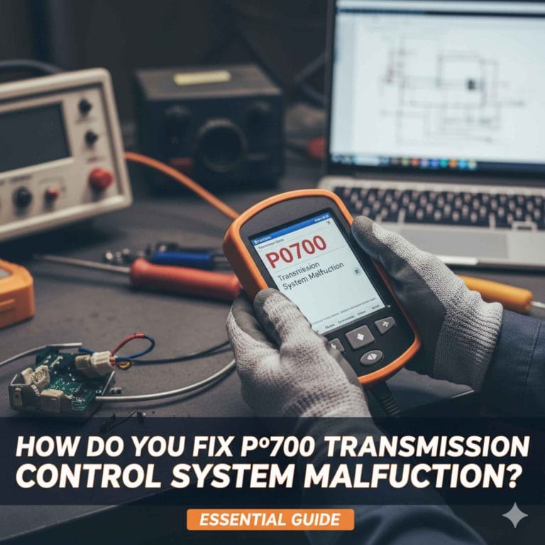
Use a failure-first transmission control system guide: verify battery voltage, scan every module, compare commanded gear to actual gear, and treat P07xx plus limp mode as an electrical or hydraulic control fault before replacing hard parts. I have seen too many guesses turn a $40 connector or speed sensor into a $1,500 TCM, valve-body, or rebuild bill. This guide walks through symptoms, scan data, wiring checks, solenoid tests, and the cheapest credible next step.
Author note: I wrote this from a first-person diagnostic perspective based on the way I would sort a real no-shift, harsh-shift, or no-reverse complaint in the bay: start with voltage, codes, live data, and wiring before blaming the module or transmission internals.
What is a transmission control system?


A transmission control system is the full electronic shift-control chain: the transmission control module, power supply, grounds, fuse protection, wiring, network communication, sensors, and solenoids. It takes in operating inputs, decides shift timing and pressure, then commands the hydraulic parts that move clutches and bands. OEM service information from manufacturers such as Ford, GM, Honda, Toyota, Stellantis, and Nissan generally describes diagnosis the same way: verify the concern, check for stored faults, inspect power and ground, and compare scan data to the commanded gear and actual ratio before replacing parts.
Transmission control system vs transmission control module
The transmission control system is the whole path from input signal to gear change. The TCM is one controller inside that path. Replacing the module will not fix a corroded connector, a blown fuse, a spread terminal, a shorted solenoid coil, or a speed sensor that drops out when hot.
That distinction matters because many failures that look like a “bad module” are outside the module. U-codes, a lost PRNDL display, harsh default shifting, or a sudden limp-home event can come from weak power, missing ground, or CAN communication trouble long before a TCM actually fails.
What the TCM reads
The TCM usually monitors turbine or input speed, output speed, range position, throttle or engine load data, brake switch status, transmission temperature, and system voltage. On some vehicles it may also monitor wheel speed or torque-reduction requests over the network. If you need background on these inputs, our pages on OBD-II codes and transmission sensors help explain how the module decides whether a shift event was normal.
Bad input data creates believable but wrong shift decisions. An output speed sensor that flatlines can make the module think the ratio is wrong. A range sensor that reports two positions at once can cause no crank, wrong-start gear, delayed engagement, or no reverse complaints.
What the TCM commands
The TCM commands shift solenoids, pressure-control solenoids, converter clutch apply, shift timing, and fail-safe strategy. In normal operation it matches commanded gear to actual ratio using sensor feedback. If the ratio, pressure response, or solenoid circuit behavior falls outside limits, it may request a warning light and trigger limp mode. That basic control strategy is consistent with OEM repair-manual logic charts and manufacturer diagnostic procedures for ratio monitoring, line-pressure control, and shift-solenoid circuit checks.
The central job is clutch pressure and torque management during shifts. That is why a bad electrical signal can feel mechanical from the driver’s seat.
What are the signs of a transmission control system problem?
Common signs are hard upshifts or downshifts, a delay going into drive or reverse, slip under load, flare during an upshift, stuck-in-one-gear operation, limp mode, no reverse, overdrive-only behavior, warning lights, and PRNDL display issues. The best clue is when the fault shows up: cold, hot, under load, during one specific shift, or only after a restart.
Harsh shifting, delayed shifting, slipping, and flare by driving condition
Harsh shifts often point to pressure-control trouble, bad load data, fail-safe operation, or adaptation values that no longer match repaired hardware. Delayed engagement after selecting drive or reverse can point to low line pressure, a leaking apply circuit, a stuck solenoid, or internal wear. Before checking transmission fluid, I prefer to capture codes and live data so the first evidence is not lost.
Flare on upshift matters because it is a ratio clue. If commanded gear changes but the input and output speed relationship does not follow, the fault family moves toward solenoid response, valve-body issues, clutch apply leakage, or worn friction elements.
Intermittent slipping only when hot often pushes diagnosis toward a sensor dropout, heat-soaked wiring near the case, or internal hydraulic loss. A fault that exists only cold can fit range-sensor alignment, sticky valves, or voltage drop during the first start of the day.
Limp mode, one-gear operation, no reverse, and overdrive-only complaints
Limp mode usually means the module has seen a fault severe enough to protect the transmission. Many units may default to a single gear, often with firm engagement and reduced converter operation. That behavior protects clutches by limiting shift activity. If you want the bigger picture on fail-safe behavior, see our guide to limp mode.
No reverse needs its own branch. If reverse is missing but forward gears work, scan data should answer one question first: does the TCM know the selector is in reverse? If yes, compare commanded reverse state with actual engagement. If no, suspect range input or related wiring before assuming internal damage.
Overdrive-only complaints and one-gear-only complaints can be electrical, hydraulic, or mechanical. The dividing line is scan data. If the TCM commands a gear but solenoid status, speed signals, and ratio do not agree, the next check depends on whether the code family is electrical or performance-related.
Warning lights, PRNDL issues, and heat-related faults
A transmission warning light may appear on its own or along with a check-engine light. Some vehicles store pending or history faults before requesting a lamp, so a driver can feel a real issue before the dash confirms it. PRNDL glitches, a blank gear display, or impossible range readings usually push diagnosis toward communication, range input, or power-feed trouble.

What should I check first for a transmission control system communication fault?
Start at the power supply. Check battery voltage with key off and while cranking, verify charging output and ripple, inspect TCM fuses, confirm module power and ground with a voltage-drop test, and see if other modules are also offline. U-codes are sorted differently from solenoid or sensor codes. A communication fault is a network or module-availability problem first, not a valve-body or clutch problem first. That order matches how OEM service manuals and many factory flow charts handle module communication faults: network health first, then local module power and ground, then connector and wiring integrity.
Battery voltage and charging faults
Low voltage scrambles module behavior. It can drop a TCM offline during crank, corrupt range information, interrupt CAN messages, and set misleading communication codes. If the complaint began after a weak battery, jump start, alternator issue, or body repair, power quality moves to the top of the list. NHTSA consumer guidance and factory service procedures both treat low system voltage as a root-cause check before deeper module replacement decisions.
Fuse, power feeds, and grounds
Check the transmission control system fuse in the fuse box or power distribution center listed for the vehicle. The amp rating should match the OEM specification. If a replacement fuse blows again, stop replacing fuses and look for a short to ground, wiring rubbed through to metal, fluid intrusion, or a shorted solenoid coil.
Ground faults are often missed. A module may still wake up enough to store partial faults while failing under load. Voltage-drop testing of powers and grounds during key-on and while moving the wiring can expose the problem faster than replacing parts.
Connector condition and CAN wiring
Look at the TCM connector, case pass-through connector, and wiring routing near engine mounts, transmission mounts, brackets, and exhaust heat. Chafing near a mount is common because the wiring flexes there every time the driveline moves.
Pin-fit problems matter too. A clean-looking connector with spread female terminals can pass a visual check and still fail current flow or data communication. On communication faults, also confirm whether the PCM, ABS, or body module shows related U-codes. One offline module changes the branch of diagnosis.
How to scan the system in the right order
Capture all codes before clearing anything
Start with an OBD-II scan tool that can read more than generic engine codes if possible. Generic tools may show some P07xx faults. Better tools can access the TCM directly, read network faults, view freeze-frame and pending codes, and run bidirectional tests. If you need a code primer first, start with our OBD-II codes page.
- Read stored, pending, and history codes from the TCM, PCM, and any module showing U-codes.
- Save freeze-frame or event data before clearing anything.
- Confirm that the scan tool communicates with the TCM. No communication is its own fault path.
- Read live data for commanded gear, input speed, output speed, range state, solenoid status, temperature, and battery voltage.
- Road test only if the vehicle is safe to move. Compare commanded gear to actual ratio behavior.
- Clear codes only after the data is captured.
Use freeze-frame, pending codes, and live data
Freeze-frame tells when the fault set: cold start, cruise, hard throttle, decel, hot soak, reverse apply, or a specific upshift. Pending codes often show a fault family before the lamp turns on. Live data separates a dead sensor from a mechanical slip faster than symptom guessing ever will.
If commanded gear changes but one speed sensor remains implausible, the sensor or its circuit moves up the list. If both speed signals look sensible but ratio still fails, hydraulic or internal mechanical trouble becomes more likely. On many vehicles, factory diagnostic procedures specifically call for comparing commanded gear, turbine speed, output speed, and calculated ratio before condemning a valve body or clutch pack.
What does the symptom-to-diagnostic table point to first?
The table starts with the symptom, then prioritizes the first three checks, the likely fault family, and the cheapest credible next path. Its main job is to stop unnecessary module or valve-body replacement when the first useful answer still sits in scan data, fuse status, or wiring inspection.
Symptom-to-diagnostic decision table
| Symptom | First three checks | Likely fault family | What comes first |
|---|---|---|---|
| Harsh shifting in all forward gears | 1) Scan TCM and PCM for P07xx and U-codes 2) Check battery voltage and TCM power/ground 3) Review line-pressure or pressure-control live data if available | Pressure-control solenoid, fail-safe operation, low voltage, adaptation mismatch | Scan tool first |
| Delayed engagement into drive or reverse | 1) Scan for pressure, range, and ratio codes 2) Verify range input matches shifter position 3) Check fluid condition only after codes and data are captured | Range sensor, pressure loss, stuck solenoid, internal apply leak | Scan tool first |
| Limp mode or stuck in one gear | 1) Read stored and pending codes 2) Confirm TCM communication 3) Check fuse, module powers, and grounds | Electrical control fault, communication fault, severe ratio error | Scan tool first |
| No reverse | 1) Verify reverse range input on live data 2) Check whether reverse is commanded 3) If command is present, compare actual response and inspect solenoid or mechanical apply path | Range sensor/wiring, reverse solenoid circuit, valve body, internal mechanical damage | Scan tool first, then wiring or mechanical based on data |
| Overdrive-only or missing specific gears | 1) Scan for shift-solenoid circuit or performance codes 2) Check input/output speed plausibility 3) Test wiring continuity to affected solenoid circuit | Shift solenoid, wiring, valve-body fault | Scan tool first |
| Warning light with U-codes | 1) Check battery and charging system 2) Check TCM fuse and grounds 3) Inspect CAN wiring and connector pin fit | Communication fault, power supply fault, module offline | Wiring and power inspection first |
| Intermittent harsh shifts when hot | 1) Save freeze-frame 2) Watch speed sensors and temperature live data 3) Inspect wiring near hot spots and case connector for fluid intrusion | Heat-related sensor dropout, connector fault, internal hydraulic change | Scan tool first, then wiring inspection |
| Fuse blows repeatedly | 1) Confirm correct amp fuse 2) Isolate load side and inspect wiring 3) Check solenoid coil for short | Short to ground, shorted solenoid, wiring damage | Wiring inspection first |
How to use the table for high-intent failure cases
No reverse, one-gear operation, and overdrive-only complaints deserve strict order. First verify that the module sees the selector correctly. Then verify whether it is commanding the expected state. Only after that should the diagnosis jump toward valve-body removal or internal teardown.
How to tell wiring, sensor, solenoid, and TCM faults apart
Sensor plausibility failures
Input and output speed sensors should tell a believable story. During launch, both change quickly but not randomly. On a steady cruise, their relationship should stabilize. If one signal drops to zero, spikes, or freezes while the vehicle behavior does not match, the sensor or its circuit becomes a leading suspect. Our transmission sensors guide goes deeper on what normal and implausible speed-sensor behavior looks like.
Range sensor plausibility is simpler: the displayed range, live-data range, and actual shifter position should agree. Mismatch here can create no reverse, wrong-gear starts, no start, or immediate limp mode.
Solenoid electrical faults and stuck behavior
Shift solenoids direct hydraulic circuits. Pressure-control solenoids modulate apply force. A stuck-open or stuck-closed solenoid can produce harsh shifts, missing gears, flare, or fail-safe operation. Circuit codes point toward electrical checks first. Performance codes push harder toward hydraulic response or valve-body trouble. OEM service procedures commonly separate these into circuit diagnostics first, then hydraulic/mechanical checks if current flow and command are normal.
Resistance checks are useful only when paired with code family and wiring integrity. A coil can measure plausibly at rest and still fail when hot, short under vibration, or stick mechanically. Bidirectional actuation tests, when the scan tool supports them, are usually more informative than resistance alone.
TCM failure symptoms vs external faults
True TCM failure becomes more credible when powers, grounds, fuse integrity, network health, and external circuits have been verified. Signs can include no communication with the TCM, impossible outputs with known-good inputs, repeated internal control-module codes, or failure to complete programming or relearn after the rest of the system checks out.
Many “bad TCM” diagnoses collapse under basic checks. External faults mimic modules every day: low system voltage, corroded connectors, fluid-wicked terminals, CAN issues, and shorted loads that drag down a driver circuit.
Why is my transmission control system warning light on?
The warning light turns on when the control system sees a fault severe enough to request driver attention or protect the transmission. That can mean a transmission-specific code, a communication fault, a sensor plausibility issue, a pressure-control problem, or a ratio error. The light explains risk, not the exact failed part.
Transmission codes, check-engine light, and stored faults
Some vehicles use a dedicated transmission lamp. Others rely on the check-engine light. A few will store pending or history faults before any lamp request, so a complaint can be real while the dash still looks normal.
If the light comes back right after clearing, suspect a hard electrical fault or active communication fault. If it returns only on a specific shift or after warm-up, freeze-frame and live data become more valuable than static checks.
Can it still be driven?
If the vehicle is in limp mode, bangs into gear, slips, or loses reverse, driving can add damage. A short trip to move it off the road is one thing. Continuing normal use without scan data is a gamble, especially when line pressure is default-high or clutch apply is inconsistent.
How do I reset a transmission control system limp mode?
Limp mode can sometimes clear after a key cycle or code clear, but that only resets the state, not the cause. If the triggering fault is still present, limp mode usually returns on the next self-check, shift event, or road test. Real repair comes from fixing the fault family that caused the protection strategy.
What resets can and cannot do
A key cycle may restore normal shifting briefly if the fault was intermittent. A scan-tool code clear may remove a stored request for fail-safe operation until the system reruns its checks. Neither action repairs a blown fuse, a dead speed sensor, a shorted solenoid, or internal clutch damage.
Will disconnecting the battery clear a transmission control system fault?
Disconnecting the battery may erase adaptive data or temporary module state, but it will not repair a hard electrical, hydraulic, or mechanical fault. It can also remove useful evidence. If the symptom changes after battery disconnect, that proves little unless the full code and freeze-frame record was captured first.
When relearn, adaptation reset, or programming is needed
After certain repairs, the TCM may need an adaptation reset or relearn. After TCM replacement, programming, VIN matching, immobilizer setup, or calibration loading may also be required depending on the vehicle. If the unit shifts worse after a battery reset but no hardware fault remains, lost adaptive values may be part of the story. Manufacturer service information often makes this explicit after valve-body work, solenoid replacement, clutch-volume-index resets, or control-module replacement.
When does the diagnosis point to repair, replacement, or internal transmission work?
Cheap-first repairs and ownership-cost context
The least expensive paid step is usually scan time, and it often prevents the expensive wrong part. Connector repair is commonly cheaper than module replacement. Sensor replacement effort usually sits below valve-body labor. Solenoid testing can be quick when external, but much heavier when access requires pan or valve-body removal.
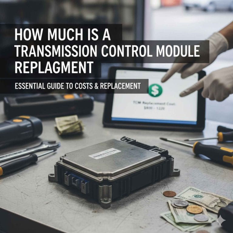
Module replacement adds cost beyond the part itself because programming and relearn work may be required. Internal transmission repair becomes the next likely step when live data is plausible, commands are correct, electrical checks pass, and the unit still shows ratio errors, no reverse, or slip tied to one clutch circuit. That is also when checking transmission fluid condition becomes more useful, because burnt fluid or debris can support the hydraulic or hard-part branch after the electrical branch has been tested.
Failure-case walkthrough: no reverse
First, verify reverse range on live data. Second, confirm whether the TCM commands reverse. Third, if command is present but reverse never applies, check the reverse solenoid circuit or pressure response. If the circuit and command are good, internal mechanical trouble moves high on the list.
Failure-case walkthrough: stuck in one gear
Start with codes. If U-codes or no TCM communication appear, stay in the communication branch. If the TCM is online and circuit codes are present, inspect fuse, powers, grounds, and solenoid circuits. If only ratio or pressure performance codes appear, mechanical or hydraulic faults become more likely.
Failure-case walkthrough: overdrive-only complaint
Compare commanded gear to actual ratio and speed-sensor behavior during the missing shift. A missing command points upstream at inputs, network data, or fail-safe logic. A present command with no gear change points downstream at the solenoid circuit, valve body, or the internal apply element for that gear set.
Frequently asked questions
Can a transmission control system cause harsh shifting?
Yes. Harsh shifting can come from pressure-control faults, fail-safe operation, low system voltage, bad load data, or a solenoid circuit problem. The key is to scan first, then compare commanded gear and pressure-related data before assuming the transmission needs internal mechanical work.
What is the difference between the transmission control system and the transmission control module?
The transmission control system includes the TCM, sensors, solenoids, wiring, grounds, fuses, power feeds, and network communication. The TCM is only the controller. A failed sensor, shorted solenoid, or corroded connector can disrupt the system while the module itself remains healthy.
What causes transmission control system wiring problems?
Common causes are chafing near mounts and brackets, fluid intrusion at case connectors, heat damage near exhaust parts, rodent damage, poor prior repairs, spread terminals, and corrosion. Wiring faults often act intermittent, especially during engine movement, vibration, hot soak, or wet weather.
Where is the transmission control system fuse located?
It is usually in the main fuse box or power distribution center, though some vehicles use more than one fuse for module power and solenoid feed. The exact cavity varies by model, so the correct diagram matters. If the replacement fuse blows again, suspect a short before replacing anything else.
Why is my transmission control system warning light on?
The light comes on because the control system detected a fault that affects shift quality, ratio control, pressure control, or module communication. It can appear with or without a check-engine light. Scan data is needed to separate a simple power-feed fault from a deeper hydraulic or mechanical issue.
What should I check first for a transmission control system communication fault?
Check battery condition, charging output, TCM fuse status, power and ground at the module, and whether other modules are offline. Then inspect CAN wiring and connector pin fit. Communication faults should be sorted before solenoids or internal transmission parts enter the discussion.
What does TCM mean?
TCM stands for transmission control module. It is the computer that interprets sensor inputs and commands shift and pressure devices. In many OEM manuals it is a standalone module, but on some vehicles the transmission controls are integrated into the PCM or mechatronic unit.
What do transmission solenoids do?
Transmission solenoids are electrically controlled valves that route or modulate hydraulic pressure. Shift solenoids select circuits for gear changes, while pressure-control solenoids fine-tune clutch apply force and shift feel. A solenoid problem can be electrical, hydraulic, or mechanical, which is why code family and live data matter.
Which sensors matter most to the transmission control system?
The most important sensors are usually input speed, output speed, range position, transmission temperature, throttle/load information, and sometimes brake switch or wheel-speed inputs. When one of these signals becomes implausible, the TCM can command harsh shifts, inhibit certain gears, or enter fail-safe operation.
Sources
- National Highway Traffic Safety Administration (NHTSA), vehicle owner information and safety defect resources related to transmission warnings, drivability complaints, and diagnostic trouble code reporting.
- OEM factory service information and wiring diagrams for Ford, General Motors, Honda/Acura, Toyota/Lexus, Nissan/Infiniti, and Stellantis transmissions, including diagnostic trees for P07xx codes, solenoid circuits, range sensors, speed sensors, and module communication faults.
- Manufacturer diagnostic procedures for adaptive relearn, control-module programming, clutch-volume or shift-adaptation resets, and ratio-monitoring tests following TCM, solenoid, or valve-body repair.
- OBD-II powertrain code descriptions and repair-manual procedures covering transmission electrical, performance, and communication faults.
Products related to this article
Sponsored / affiliate links. As an Amazon Associate I earn from qualifying purchases. I may earn additional commission from eligible campaigns.
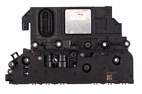 24275869 Transmission Control Module TCM Compatible with GM 6T70 6T75 6T80
 XYZIL 12 Pin 4 Speed Transmission Controller Shift Range Selector 8223049 Compatible with JLG Lull 1044C-54 6036 6042 10054 10042 8042 w/ DT06-12S Plug Compatible with Skytrak 4266 4270 4290 Forklift
 Astibym 4L80E Transmission Controller Full Manual Shift 4L80E NCR80E