Transmission Control System Wiring Problems: Signs and Fixes
Transmission control system wiring problems usually show up as intermittent shifting faults, multiple gear codes, no-communication faults, or symptoms that change when you wiggle the wiring; check power, ground, and CAN circuits first before replacing the TCM or opening the transmission. Ignoring them can lead to repeated misdiagnosis, unnecessary module swaps, and expensive internal repairs that won’t fix a broken wire or corroded connector. This guide covers common signs by circuit type and the quickest fixes for wiring, connector, and ground faults.
What transmission wiring faults do

The TCM is generally responsible for shift timing and line pressure. It depends on clean power, a solid ground, and believable sensor and network signals. When any of those circuits go bad, the transmission can shift harshly, delay shifts, refuse to upshift, or stay stuck in one gear.
That failure can look like a bad module, a bad solenoid pack, or a failed sensor. Wiring faults can also trigger limp mode or reduced performance mode, which is why circuit type matters before parts replacement.
Why power, ground, and signal circuits matter
Power and ground feed the module and solenoids. Sensor circuits tell the TCM what the transmission is doing. CAN bus circuits let the TCM talk to the rest of the vehicle. A fault in any one of those paths can create codes that point in the wrong direction.
Heat, rubbing, corrosion, and moisture are common trouble spots in the transmission wiring. External damage is common near the battery tray, underbody, radiator support, and transmission case.
How a wiring fault can mimic a bad TCM
A low-voltage feed can brown out the TCM and create communication codes. A poor ground can make the module reboot or misread inputs. A shorted control wire can make a solenoid look failed even when the solenoid itself is fine.
That is why P0700 often appears with another code that points to the real fault, and why U0100, U0101, or U0140 should prompt a full module scan rather than a single-code guess.
What you’ll need
- Scan tool with live data and code access
- Multimeter
- Wiring diagram for the exact vehicle
- Back-probe leads
- Basic hand tools
- Contact cleaner
- Repair supplies for wire and connector repair
Transmission wiring fault matrix
| Symptom pattern | Probable cause | Exact meter check | Inspect first | Most likely repair |
|---|---|---|---|---|
| Intermittent limp mode | Power, ground, or CAN drop-out | Voltage drop on TCM feed and ground under load | External wiring | Repair rubbed wire, corroded connector, or bad ground |
| Blown fuse returns | Short-to-ground or chafed power wire | Ohms to ground on the fused circuit with power off | Connector | Locate short, repair insulation damage, replace fuse only after fault repair |
| No communication | Lost module power, ground, or CAN bus issue | Battery voltage at module pins and CAN resistance check | Ground | Restore power feed, ground, or network continuity |
| Harsh shifts after rain | Moisture intrusion in wiring or connector | Voltage drop and continuity after connector separation | Connector | Dry, clean, seal, or replace connector and affected wire |
| Gear indicator errors | Range sensor signal fault or wiring defect | Live PRNDL data and continuity on range sensor circuits | External wiring | Repair range sensor wiring, then verify adjustment |
Can bad wiring cause a transmission to go into limp mode?
Yes. Wiring problems can trigger limp mode or reduced performance mode when the TCM loses a power feed, a ground, or a valid signal. The module may choose a default strategy to protect the transmission when it cannot trust its inputs.
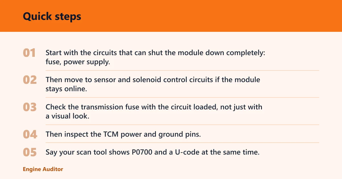
Start with the circuits that can shut the module down completely: fuse, power supply, ground, and CAN communication. Then move to sensor and solenoid control circuits if the module stays online.
Which circuits to check first when it appears?
Check the transmission fuse with the circuit loaded, not just with a visual look. Then inspect the TCM power and ground pins, because low battery or ground voltage can brown out the module and create communication codes.
Say your scan tool shows P0700 and a U-code at the same time. That pattern points to a module or network fault path, not a single bad shift feel complaint.
How do you test the circuit?

Use a multimeter, a wiring diagram, and a scan tool. Voltage-drop testing is part of proper transmission wiring diagnosis because it finds high-resistance power and ground faults that still show continuity on a simple ohm check.
Check fuses and power feeds under load
- Key off, inspect the transmission and TCM fuses in the fuse box shown on the diagram.
- Install the meter leads on both sides of the fuse or at the power pin and ground.
- Key on, engine running if the diagram requires it, and read battery voltage at the feed.
- If the fuse fails again, stop and trace the circuit for a short-to-ground.
A blown fuse that returns after replacement is a key clue for wiring trouble. Do not keep installing fuses without finding the short.
Measure ground and power voltage drop
- Set the meter to volts.
- Back-probe the module ground and battery negative while the circuit is active.
- Read voltage drop on the power side from battery positive to the module feed.
- Repeat at the solenoid pack or range sensor if the diagram shows separate feeds.
High resistance often shows up only under load. A good-looking connector can still fail a voltage-drop test.
Inspect connectors, routing, and moisture points
- Follow the wiring from the TCM to the transmission case using the routing shown on the diagram.
- Check areas near the battery tray, underbody, radiator support, and transmission case for rubbing or heat damage.
- Separate connectors, inspect for green corrosion, spread terminals, or water, then clean and reseat them.
- Repair damaged insulation or replace the connector if locking tension is weak.
Picture a car that shifts normally in dry weather, then goes harsh after a heavy rain. Moisture in a connector is often the first thing to inspect, not the TCM.
Verify sensor and solenoid signals with live data
Watch input and output speed sensor data for plausibility. Bad wiring can create believable but wrong data, which may produce ratio or communication codes alongside the shift complaint. Range sensor data should match the shifter position on the PRNDL display.
Shift solenoids depend on intact control wiring. Shared power or ground faults can create multiple codes at once, so do not condemn the solenoid until the control circuit proves clean.
How do you separate wiring from TCM or solenoids?
Use code patterns and live data together. A module that loses power, ground, or communication is not the same problem as a failed solenoid circuit. A TCM can fail from wiring faults, low voltage, or internal damage, but the module should be proven bad before replacement.
Use code patterns and live data together
U0100, U0101, and U0140 point to communication trouble, but they do not prove a bad TCM by themselves. Scan all modules, not just the transmission, to see whether the network fault is isolated or shared.
If the TCM is online but the speed sensor data is implausible, inspect the sensor wiring and connector before replacing the sensor or module.
Decide whether the fault is external, connector, ground, or internal first
External wiring faults are common when the damage is visible near heat, movement, or moisture. Connector faults often show up as intermittent symptoms when the wiring is touched or shaken. Ground faults tend to create multiple strange symptoms at once.
Internal transmission wiring becomes more likely when the external wiring and connector checks pass, but the fault stays tied to the transmission case or internal pass-through. That is where a wiring diagram matters most.
When a module replacement is actually justified
Replace the TCM only after power, ground, CAN, and sensor circuits test correctly and the fault remains with the module. A standalone TCM may cost $180-450 for the part, with $80-180 flash labor. A mechatronic module may total $900-1,800 including programming and adaptation.
After a TCM swap, adaptive relearn is needed to restore proper shift quality. Miss that step, and the vehicle may still shift poorly even though the wiring fault is fixed.
Common mistakes
- Replacing the TCM before checking fuses, power, ground, and CAN continuity.
- Using visual inspection alone instead of voltage-drop testing.
- Ignoring intermittent faults that appear only with heat, vibration, rain, or engine movement.
- Forgetting that a repeated blown fuse usually means an active short, not a random failure.
- Skipping adaptive relearn after a repair or module replacement.
If that didn’t work, move from external wiring checks to connector inspection, then to ground and network testing, and only after that consider internal transmission wiring or module replacement. Electrical surges from a faulty alternator or bad jump-start can also damage control circuits, so confirm charging-system health if the fault began after a jump or battery event.
Frequently asked questions
What are the common signs of transmission control system wiring problems?
Common signs include harsh shifting, delayed shifting, no upshift, stuck-in-gear behavior, and warning lights tied to transmission or engine codes. Intermittent symptoms that change with rain, vibration, or wiring movement often point to wiring rather than a hard mechanical failure.
Can wiring issues cause harsh or delayed shifting?
Yes. A bad power feed, ground, speed sensor signal, or solenoid control wire can change shift timing and line pressure commands. If the shift behavior changes after a connector move or water exposure, inspect the wiring and voltage drop before replacing parts.
What codes point to transmission wiring problems?
P0700 often appears with another code that identifies the real fault. Ratio, sensor, or solenoid codes can also come from wiring faults, so check live data and power supply first.
Can a blown fuse cause transmission control problems?
Yes. A blown fuse can cut module or solenoid power and cause no-shift or limp mode symptoms. If the fuse returns after replacement, treat it as a short in the circuit and trace the wiring, connector, and load side before installing another fuse.
How do you test transmission wiring with a multimeter?
Use the wiring diagram, then check voltage at the module feed and perform voltage-drop testing on the ground and power side with the circuit active. Finish with continuity checks only after the power is off. That order finds high-resistance faults that simple resistance checks can miss.
Where do transmission wiring problems usually happen?
They often happen near the battery tray, underbody, radiator support, and transmission case. Those areas see heat, rubbing, corrosion, and moisture. Internal case wiring faults are less common, so inspect the external wiring and connectors first unless the symptoms clearly point inside the transmission.
Products related to this article
Sponsored / affiliate links. As an Amazon Associate I earn from qualifying purchases. I may earn additional commission from eligible campaigns.