Input Speed Sensor vs Output Speed Sensor: Which Controls?
The transmission control module uses both sensors, but it often relies more on the output speed sensor for gear-ratio checks and fail-safe decisions, while the input speed sensor mainly tracks turbine speed and shift timing. Miss that split, and you can replace the wrong part, keep limp mode active, or overlook a fault that only affects the speedometer. This guide shows how to tell control-data faults from speedometer-only faults, which codes point to each sensor, and how to test both without special equipment.
Input speed sensor vs output speed sensor: the control-data trade-off
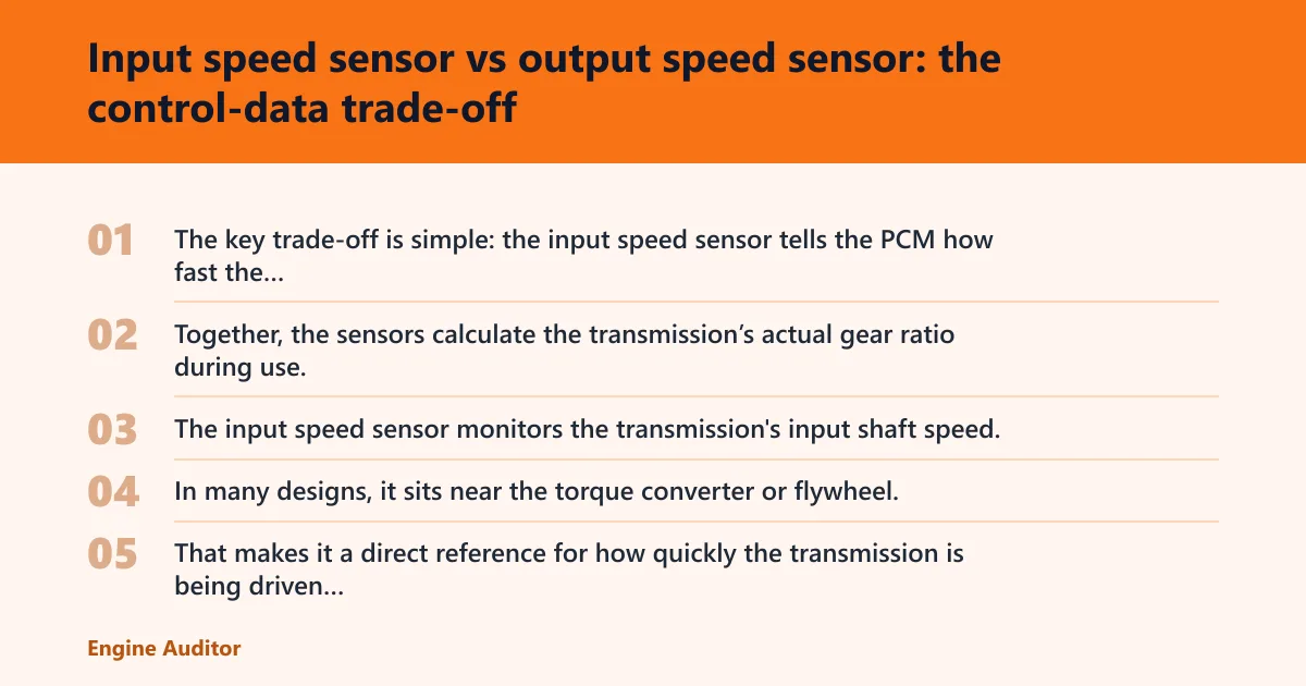


The key trade-off is simple: the input speed sensor tells the PCM how fast the transmission’s input shaft is turning, while the output speed sensor tells it how fast the output shaft is turning. Together, the sensors calculate the transmission’s actual gear ratio during use, so a mismatch can trigger ratio-plausibility faults, strange shift behavior, or fail-safe action.
| Decision factor | Input speed sensor | Output speed sensor | Winner |
|---|---|---|---|
| What it measures | Transmission input shaft speed | Transmission output shaft speed | Tie |
| Main control role | Shift timing and ratio validation | Vehicle speed information and ratio validation | Output speed sensor |
| Most obvious symptom when faulty | Harsh, delayed, or failed shifts; limp mode | Speedometer errors, odd cruise behavior, or speed-related fail-safe | Tie |
| Typical signal behavior | May generate an AC voltage signal | May generate a digital or square wave signal | Tie |
| Best first check | Scan data and wiring near the transmission | Scan data, then reluctor ring and loom inspection | Tie |
What the input speed sensor measures
The input speed sensor monitors the transmission’s input shaft speed. In many designs, it sits near the torque converter or flywheel, and some versions generate an AC voltage signal that changes with shaft speed. That makes it a direct reference for how quickly the transmission is being driven internally.
Because that signal reflects turbine or input speed, the PCM can compare it with output speed and decide whether the commanded gear makes sense. When that comparison fails, the control module may change shift strategy or limit operation to protect the transmission.
What the output speed sensor measures
The output speed sensor monitors the transmission output shaft. Its signal provides vehicle speed information, and many designs generate a digital or square wave signal. That makes it the sensor most directly tied to speedometer accuracy and vehicle-speed reporting.
It still matters for shift control. The PCM uses output speed together with input speed to verify the gear ratio. If the output signal drops out, the module may lose confidence in road speed and fall back to fail-safe behavior.
How the PCM compares the two signals
The powertrain control module uses both speed sensor signals, compares input and output data for gear ratio, and reacts to discrepancies in transmission operation. That comparison is the control-data check that separates a real ratio problem from a sensor or wiring problem.
Picture a typical multi-speed automatic in a middle gear. If input speed rises normally but output speed stays flat or flickers, the PCM may decide the ratio is implausible and protect the transmission. That is why the fault code matters, but live data matters just as much.
Which speed sensor affects shifting and fail-safe decisions most?
The input speed sensor usually has the more direct effect on shift quality and fail-safe decisions, because the PCM uses it to track internal transmission speed and validate gear changes. The output speed sensor still matters, but it more often drives vehicle-speed information and speedometer behavior than the shift event itself.
Why the input speed sensor can drive gear-ratio faults
Shift control depends on knowing how fast the input shaft is turning during a commanded shift. If that signal is missing, noisy, or out of step with output speed, the PCM may see a ratio error and default to a protective strategy. That is why a bad input sensor often shows up as delayed shifts, harsh shifts, or limp mode.
Why the output speed sensor can trigger vehicle-speed errors
The output sensor signal is used to determine vehicle speed, so a failure often shows up as a speedometer issue first. It can still affect shifting because the PCM needs a believable output-speed signal to validate gear ratio, but a speedometer fault points more strongly to the output side than to the input side.
How the PCM decides whether to protect the transmission
When input and output data disagree beyond what the gear command allows, the PCM may store a ratio code and switch to fail-safe logic. That protection can include fixed gears, delayed shifts, or disabling certain operating states until the signal pattern looks believable again.
What symptoms point to input sensor, output sensor, wiring, or reluctor-ring faults?
Use the symptom pattern, not the part name on the code, to narrow the fault. Harsh or delayed shifting points more toward the input side or a control-data mismatch, while a speedometer fault with normal shift quality points more toward the output side. Intermittent problems often come from wiring or connectors, not the sensor itself.
Harsh shift, delayed shift, or limp mode
These symptoms often point to the input speed sensor because the PCM relies on that signal to judge shift timing and gear ratio. If the signal is missing or implausible, the module may treat the transmission as unreliable and go into fail-safe mode.
A common first-timer mistake is to replace the speed sensor after a single code scan and skip the live-data check. If the input and output values move normally during a road test, the fault may be in the wiring loom, connector, or control logic instead.
Speedometer error with normal shift quality
A bad output speed sensor can make the speedometer act up because that sensor provides vehicle speed information. If shifting still feels normal and the transmission does not enter limp mode, the output side becomes a stronger suspect than the input side.
Suppose the speedometer drops to zero for a few seconds while the truck still shifts cleanly. That pattern fits an output-speed signal issue, a connector problem, or damage at the reluctor ring more than an input-sensor failure.
Intermittent fault that changes with wiring movement
When the symptom appears or disappears as the wiring moves, the wiring loom and connectors become prime suspects. Corrosion, broken conductors, poor pin tension, or fluid intrusion can mimic a dead sensor by interrupting the signal path.
That kind of fault often creates inconsistent live data rather than a hard zero. The scan tool may show brief dropouts or spikes that do not match actual road speed.
Debris, damage, or gap issues at the reluctor ring
Output-speed diagnosis includes checking the reluctor ring. Missing teeth, metal debris, or an excessive air gap can distort the waveform and make a good sensor look bad. That is especially important when the scan data shows erratic speed only at certain road speeds.
Decision table: codes, live data, and the most likely fault
Use stored codes, live data, and a short road test together. A code alone may point to the circuit the PCM saw fail, while live data tells you whether the sensor, wiring, reluctor ring, or control module is the real problem.
| Real-world symptom or scan pattern | Common DTC pattern | Live-data behavior | More likely fault |
|---|---|---|---|
| Harsh shifts, delayed upshifts, limp mode | Input speed or ratio-related codes | Input speed missing, erratic, or not plausible for gear | Input sensor |
| Speedometer inaccurate, but shifts feel normal | Output speed or vehicle-speed codes | Output speed zero, stuck, or jumping while input looks normal | Output sensor |
| Fault changes when wiring is wiggled | Any intermittent sensor code | Signal dropouts, sudden spikes, or momentary loss | Wiring or connectors |
| Output signal looks noisy at one road speed only | Output speed or ratio code | Waveform distorts or pulses unevenly | Reluctor ring |
| Codes return after sensor replacement | Repeat input/output fault plus plausibility code | Both signals look electrically present, but ratio still fails | PCM or TCM logic |
DTC patterns that lean toward an input sensor fault
Codes that point to input speed or turbine speed usually matter most when shift quality changes at the same time. If the PCM cannot trust input speed during a shift event, it may also log ratio or performance faults because the gear calculation no longer makes sense.
DTC patterns that lean toward an output sensor fault
Output-speed or vehicle-speed codes fit speedometer complaints, erratic cruise operation, or a road-speed display that drops out. Because the output signal is used to determine vehicle speed, those symptoms often appear before obvious shift trouble.
Live-data patterns that point to wiring or connector issues
If live data flickers, drops to zero for a split second, or changes when the wiring is moved, suspect the circuit before the sensor. Corrosion, backed-out terminals, and broken conductors can interrupt a clean signal without leaving obvious external damage.
When PCM or TCM logic becomes the suspect
If both signals are present, the connectors are sound, the reluctor ring looks correct, and the same ratio fault returns, the control module becomes the next suspect. That is less common than sensor or wiring faults, but it matters when the data pattern is internally inconsistent rather than physically missing.
How do you test an input or output speed sensor?
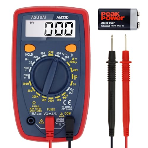
Start with an OBD-II scanner, then inspect wiring and connectors, then test the sensor signal with the right tool. A multimeter can read AC voltage on some input speed sensors, while an oscilloscope is typically used to test the output speed sensor and confirm square-wave behavior.
- Scan for stored and pending codes with an OBD-II scanner.
- Record live input speed, output speed, and vehicle speed at idle and during a short road test.
- Inspect the wiring loom and connectors for corrosion, bent pins, fluid intrusion, or broken insulation.
- Check the reluctor ring on output-speed systems for debris, missing teeth, or damage.
- Use a digital multimeter on sensors that output AC voltage.
- Use an oscilloscope to confirm the output sensor’s square-wave pattern when the scan data looks wrong.
Start with an OBD-II scan
An OBD-II scanner is recommended for checking stored error codes, and it is the fastest way to decide whether the fault is transmission control data or a vehicle-speed issue. Write down code numbers and freeze-frame data before clearing anything.
Check wiring loom and connectors
Common failure points include corrosion, broken wires, and loose connectors. A sensor can test fine on the bench and still fail in the vehicle because the circuit opens only when heat, vibration, or movement disturbs the wiring loom.
Use a digital multimeter on AC-output sensors
A digital multimeter can be used to test the sensor output signal, especially on input speed sensors that may generate AC voltage. That test helps confirm whether the sensor is producing a changing signal, but it does not always reveal waveform quality under load.
Use an oscilloscope for output-speed signals
An oscilloscope is typically used to test the output speed sensor because it shows square-wave shape, dropouts, and noise that a basic meter can miss. If the waveform is broken, the issue may be the sensor, the reluctor ring, or the circuit feeding the PCM.
Choose input speed sensor if… / Choose output speed sensor if…
Choose the input speed sensor if the main complaint is harsh shifting, delayed shifts, ratio codes, or limp mode tied to shift events. Choose the output speed sensor if the speedometer is wrong, road-speed data is unstable, or the fault appears mainly in vehicle-speed reporting. If live data points to signal loss only when the wiring moves, stop at wiring or connector inspection first.
Choose input speed sensor if…
The transmission shifts poorly, the scan tool shows input or ratio faults, and the output signal still looks believable. That combination means the PCM is losing trust in internal transmission speed data, which pushes the input sensor higher on the list.
Choose output speed sensor if…
The speedometer misbehaves, vehicle speed reads wrong on the scan tool, or the fault appears at certain road speeds only. Because the output sensor supplies vehicle speed information, those clues point away from the input sensor and toward the output side, the reluctor ring, or its wiring.
When to stop at wiring or reluctor-ring inspection instead
Stop chasing sensors if the fault comes and goes with wiring movement, if the connector pins look corroded, or if the output waveform shows a clean sensor but a bad target ring. Those are circuit or mechanical target problems, and a new sensor will not fix them.
Frequently asked questions
What is the difference between the input speed sensor and the output speed sensor?
The input speed sensor monitors the transmission’s input shaft speed, while the output speed sensor monitors the transmission output shaft speed. Together, the sensors calculate the transmission’s actual gear ratio during use. The input side is more about shift control; the output side is more about vehicle speed.
Which speed sensor affects shifting and control the most?
The input speed sensor often has a larger effect on shift timing and fail-safe decisions because the PCM may use it to validate internal transmission speed during a shift. The output sensor still matters for ratio checks, but a bad input signal more often creates harsh shifting or limp mode.
Can a bad input speed sensor cause limp mode?
Yes. If the PCM cannot trust input speed, it may see the gear ratio as implausible and switch to fail-safe operation. That can limit shifting, hold a single gear, or otherwise protect the transmission until the signal becomes believable again.
Can a bad output speed sensor make the speedometer act up?
Yes. The output speed sensor signal is used to determine vehicle speed, so a bad output sensor can create a dead, erratic, or inaccurate speedometer. It can also affect shift decisions if the PCM loses a reliable road-speed reference.
How do you test an input or output speed sensor?
Start with an OBD-II scanner, then inspect the wiring loom and connectors, then check live data during a road test. A digital multimeter can read AC voltage on some input speed sensors, and an oscilloscope is typically used to confirm output-speed square-wave behavior.
Are input and output speed sensors interchangeable?
No. The sensors are not interchangeable because signal type, location, and control role differ. The input sensor may sit near the torque converter or flywheel and may generate AC voltage, while the output sensor monitors the output shaft and may generate a digital or square-wave signal.
What codes point to an input speed sensor or output speed sensor fault?
Codes that mention input speed, turbine speed, output speed, vehicle speed, or transmission ratio are the main clues. The exact code family varies by vehicle, so the safer approach is to match the code with live data and symptom pattern instead of treating every speed code the same.
Can wiring or connectors make a good sensor look bad?
Yes. Wiring loom and connector problems are common failure points, and corrosion or broken wires can mimic a failed sensor. If the live signal drops out when the wiring is moved, the circuit should be checked before the sensor is replaced.
Which sensor should I check first for harsh or delayed shifting?
Check the input speed sensor first, along with its wiring and connector, because it has the stronger link to shift timing and gear-ratio validation. If the speedometer is also wrong, add the output speed sensor and the reluctor ring to the top of the list.
What symptoms mean the transmission control module is reacting to bad speed data?
Typical signs include limp mode, harsh or delayed shifts, unexpected gear holding, and codes that point to ratio or plausibility problems. When the module cannot reconcile input and output speed data, it may protect the transmission rather than continue normal shifting.
Products related to this article
Sponsored / affiliate links. As an Amazon Associate I earn from qualifying purchases. I may earn additional commission from eligible campaigns.
 MecXora 24203876 Automatic Transmission Input and Output Speed Sensor & Wiring Harness Kit Compatible with Select GM Chevy GMC Cadillac Isuzu Workhorse Models Replaces#24203876 8661628 8683265
 Transmission Input Speed Sensor 24244544 D74438E Compatible with GM 4L60E 4L65E 4L70E Automatic Transmission 2005-Up ISS Replacement