Transmission Control Module Not Communicating: Likely Causes
A transmission control module that is not communicating is most often caused by a blown fuse, bad power or ground, a damaged CAN bus circuit, corrosion at a connector, or a module fault. U0101 is a generic loss-of-communication code, not automatic proof of a failed TCM, and OEM service information should always be used to confirm the exact pinout, fuse name, and voltage specs for the vehicle before probing [1][2][3].
- Confirm battery voltage and charging output are stable.
- Check the TCM fuse with the key off and key on.
- Verify battery feed at the TCM connector.
- Verify ignition feed where the design requires it.
- Only then move to ground and network checks.
Start with those five checks because they catch the most common causes fastest and avoid unnecessary parts swapping. CAN readings, TCM location, fuse names, and line voltages vary by platform, so confirm the vehicle’s service data before measuring or backprobing anything [1][2][3][4].
What does transmission communication loss mean?
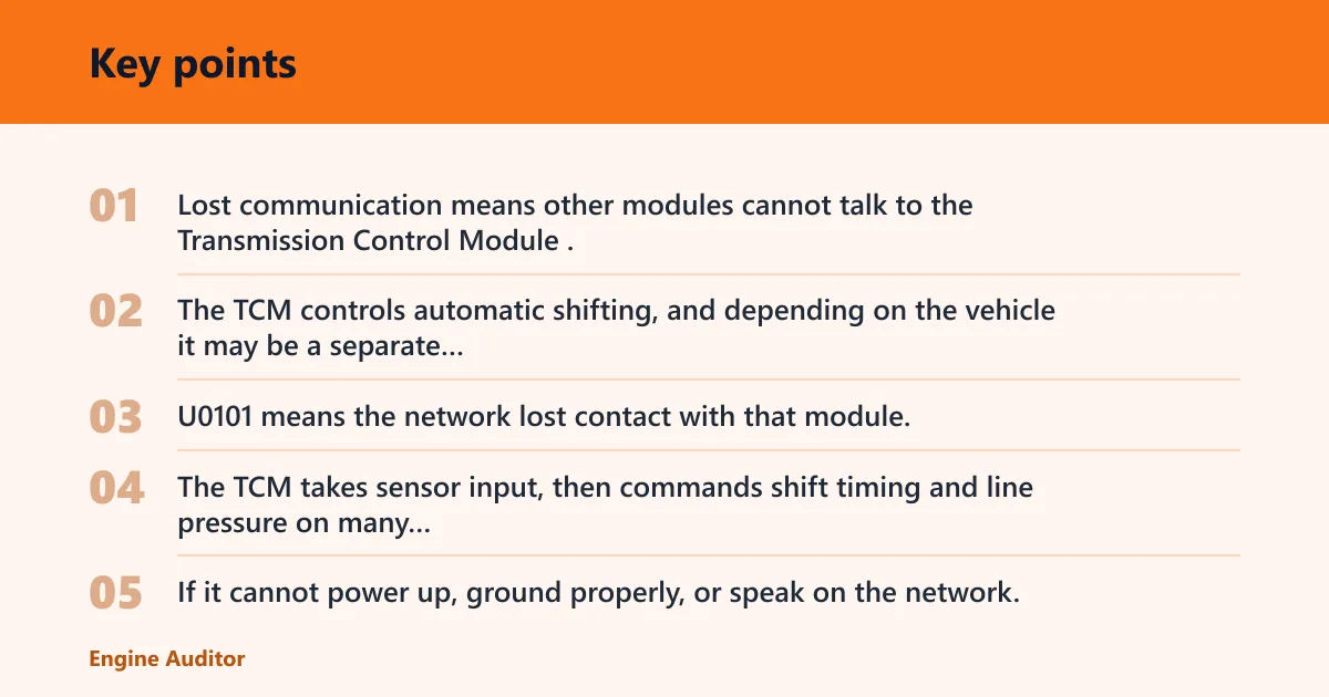


Lost communication means other modules cannot talk to the Transmission Control Module. The TCM controls automatic shifting, and depending on the vehicle it may be a separate unit, built into the transmission, or combined with the PCM. U0101 means the network lost contact with that module; it does not by itself prove the module is bad [1][2].
How the TCM fits into shifting control
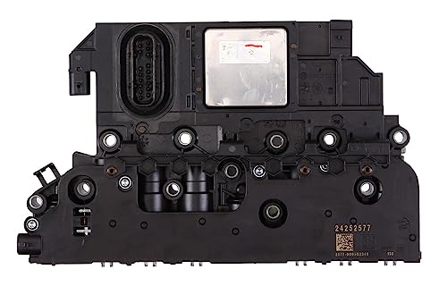
The TCM takes sensor input, then commands shift timing and line pressure on many automatic transmissions. If it cannot power up, ground properly, or speak on the network, shift control falls apart quickly. On some vehicles, the TCM is external and easier to inspect. On others, it is internal or combined with the PCM, so service information must confirm the layout before testing [1][2][4].
Why U0101 points to communication loss
U0101 is a generic network communication code. It does not prove that the module is bad. It only means the other modules lost contact with the TCM. OEM and scan-tool references treat it as a loss of communication between controllers, which is why power, ground, and network integrity must be checked first [1][2].
What limp mode looks like
Limp mode is the drivetrain’s fallback strategy. The vehicle may stay in one gear or shift very little so it can keep moving with less risk of damage. A check engine light often appears with the code, and the transmission behavior may feel harsh or locked down rather than normal [2][3].
Say the vehicle leaves normally, then after about a 10-minute stop-and-go commute it may stick in second gear and the scan tool may show U0101. That pattern fits fail-safe behavior, but it still does not tell you whether the cause is low voltage, a bad ground, a CAN bus fault, or an internal module problem [1][2].
Can a weak battery cause this problem?
Yes. Low battery voltage can interrupt module communication, and charging system problems can mimic a failed TCM. Before deeper diagnosis, verify battery state and charging output. If system voltage is unstable, multiple modules can drop offline at once, and the transmission controller may look guilty when it is only underpowered [2][4].
Battery voltage checks before module diagnosis
Check the battery first, then the charging system. A weak battery can pull module voltage low enough to stop communication, especially during cranking or after sitting. If the vehicle cranks slowly, the dash lights dim hard, or several warning lamps appear together, treat low voltage as a top suspect. Confirm the vehicle’s specified battery and charging targets in service information [1][3][4].
Charging system problems that mimic a failed TCM
An alternator or charging circuit problem can create the same symptom pattern as a bad module. That matters because a scan tool may report communication faults while the real issue is unstable voltage under load. Fixing voltage supply problems first prevents wasted parts and false conclusions [2][4].
Suppose the battery is only a year old, but the charging lamp comes on and the scanner shows communication loss plus unrelated low-voltage codes in other modules. That pattern leans away from the TCM itself and toward supply-side trouble, though the exact low-voltage threshold still varies by vehicle and should be checked in the service data [1][4].
Should you check the TCM fuse and power supply first?
Yes. A blown fuse can kill communication immediately. Check the TCM fuse and the power supply circuit before blaming the module. Verify both battery feed and ignition feed, because a fuse can be intact while the circuit still lacks the correct supply at the connector. Fuse names and circuit IDs vary by platform, so confirm the exact one in service information [1][3][4].
Battery feed and ignition feed tests
Use a scan tool, wiring diagram, or fuse chart to identify the correct power circuits, then test for voltage at the fuse and at the TCM connector. A fuse that looks good can still have no power on either side if the circuit is open upstream. Confirm battery feed first, then confirm ignition-switched feed when the key is on, using the vehicle’s specified test points [1][4].
What a blown fuse means and what it does not mean
A blown fuse means the circuit lost protection because current was too high, or the fuse failed for another electrical reason. It does not automatically mean the TCM failed. If the replacement fuse blows again, stop and look for a shorted wiring run, water intrusion, or a failed internal circuit before installing another fuse [3][4].
A scan tool or OBD2 reader should read codes from all modules, not only the engine computer. OBD Spark recommends scanning all control modules for additional communication codes. That wider scan helps separate a dead power feed from a true network fault [2].
Should you check the TCM ground and connector next?
Yes. A poor ground can stop communication just as effectively as a bad fuse. Test the TCM ground connection with resistance and voltage drop checks, then inspect the connector and wiring run for corrosion, loose pins, pinched wiring, and water intrusion. Ground locations, splice points, and acceptable voltage-drop values vary by vehicle, so verify them in service information before condemning the circuit [1][4].
Ground resistance and voltage drop checks
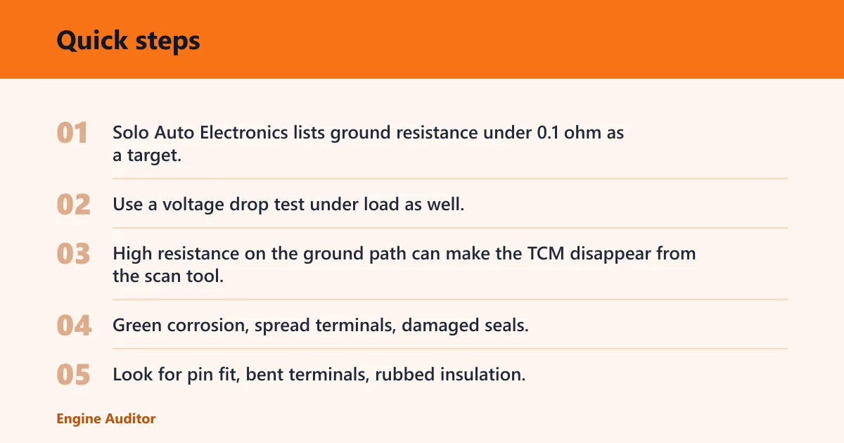
Solo Auto Electronics lists ground resistance under 0.1 ohm as a target, but that should be treated as a general benchmark, not a universal spec. Use a voltage drop test under load as well, because a ground that looks acceptable with the key off can fail when the module wakes up. High resistance on the ground path can make the TCM disappear from the scan tool [4].
Corrosion, loose pins, and water intrusion
Inspect the connector closely. Green corrosion, spread terminals, damaged seals, or damp housing points to a connection problem, not necessarily a dead controller. Look for pin fit, bent terminals, rubbed insulation, and wiring sections that flex near brackets or the transmission case. Sun Transmissions specifically calls for inspecting CAN bus wiring for damage [3].
Picture a crossover that sat through a deep puddle event. The fuse checks good, the battery is healthy, but the transmission connector has moisture and one terminal is darkened. That kind of damage can interrupt communication without leaving a dramatic visible break, especially on vehicles where the TCM sits low on the case or in a splash-prone harness route [1][3].
Is U0101 always a bad TCM?
No. U0101 is not proof of an internal TCM failure. It is a network code, and related codes from other modules matter a lot more than the single code alone. Multiple control modules may report loss of communication with the TCM, or the TCM may be absent because power, ground, or network wiring failed first [1][2].
How to read related codes from all modules
Scan every module that the tool can reach. If several modules report communication faults at the same time, especially alongside low-voltage or network codes, the problem often sits in shared wiring, power distribution, or the CAN bus rather than inside the TCM. That is why a full-module scan is better than a quick engine-only readout [2][3].
Which code clusters point to power, ground, or network faults?
Codes tied to low voltage, multiple lost-communication messages, or several modules going offline together point away from a single bad controller. If only the TCM is missing and the rest of the network is healthy, module power, module ground, or the TCM itself moves higher on the list. If many modules vanish together, suspect the network backbone, a splice, or a shared power supply [1][2][4].
Common misdiagnosis: U0101 is often mistaken for “bad TCM,” but a dead module is only one possibility. Shared power, ground, or network faults can take the TCM offline while the module itself is fine, which is why replacing the part before checking the circuit is the most common expensive mistake [1][2][3].
Transmission CAN bus diagnostic table
This table gives you a triage order. Start with the fastest failure modes first. Use the pattern, not the code alone, to decide whether to keep testing at home or stop and escalate. CAN resistance, expected line voltage, and even which modules share the network can vary by platform, so confirm the exact specs before testing [1][4].
| Symptom/pattern | Most likely cause | Likely scan pattern | Probable voltage findings | First test | Next action |
|---|---|---|---|---|---|
| No communication at all with the TCM | Blown fuse, missing power feed, bad ground, or open connector | U0101 alone or with a single module complaint; TCM absent from scan | Missing B+ or ignition feed at the connector; weak or unstable ground under load | Check battery voltage, then verify fuse power and ground at the TCM connector | If power and ground are present, inspect CAN wiring and connector pins; if several modules are also offline, stop and escalate |
| Intermittent communication | Loose pin, corrosion, broken strand in wiring, water intrusion | U0101 returns after bumps, heat soak, rain, or harness movement | Voltage and resistance may look normal until the harness moves; dropouts appear during wiggle testing | Wiggle-test the wiring run while watching live communication and volt drop | Repair the affected section; if the fault changes with wiring movement near the transmission, inspect for chafe or stretch damage |
| Limp mode with U0101 | Lost network link, low battery voltage, or the TCM losing power under load | U0101 with shift-lock or fail-safe complaints; may coexist with low-voltage or module voltage codes | System voltage dips during crank or load; feed may disappear only when the circuit is stressed | Scan all modules and check battery and charging output first | If voltage is stable and the code returns, test CAN bus resistance and connector condition before suspecting the module |
| Multiple module codes | Shared CAN bus fault, shared power supply problem, or system-wide voltage drop | Several modules report lost communication at once | Network resistance or line voltage out of range; shared feed or ground may be missing | Check for common power, ground, and network points used by more than one module | Stop DIY testing if several modules cannot communicate; a shop may need network-level testing and pinpoint fault isolation |
When to stop DIY testing and send it to a shop
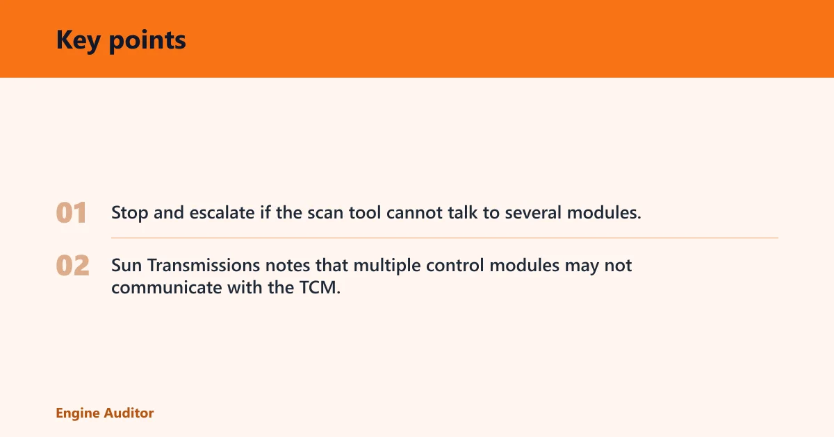
Stop and escalate if the scan tool cannot talk to several modules, if CAN resistance is far from the expected total, or if repeated fuse failures point to a short you cannot isolate quickly. Sun Transmissions notes that multiple control modules may not communicate with the TCM, and that pattern usually needs deeper network diagnosis than a casual parts swap [3][4].
How do you diagnose a CAN bus problem?
Check the CAN bus after power and ground are verified. The CAN bus is the module-to-module communication network, and it can be tested for voltage, resistance, shorts, and wiring damage. The same source lists about 60 ohms total resistance and about 2.5V on each CAN line as common reference points, but those values can vary by vehicle and must be confirmed in service information before interpreting a reading [4].
Voltage and resistance checks on the network
Use the service information for the exact pinout, then measure resistance across the bus with the system powered down as directed by the vehicle procedure. If the total reading is far from the expected value, there may be an open, short, or termination problem. Voltage checks on the individual lines help separate a network fault from a missing module supply, but the exact test points and acceptable ranges vary by platform [1][4].
Shorts, opens, and wiring damage near the transmission
Inspect the wiring run where it bends, clips to the body, or routes past the transmission case and exhaust heat. Damaged CAN bus wiring is a common cause of U0101, and even a rubbed-through conductor can interrupt communication only when the engine moves or the wiring shifts. That creates a fault that comes and goes with vehicle movement, so a static visual inspection is not enough [3][4].
Should you replace the TCM first?
No. Replace the TCM only after battery, fuse, ground, connector, and CAN checks pass. The module may be external, integrated into the transmission, or combined with the PCM, so replacement can be expensive and awkward. If the supply and network test good and the TCM still will not talk, the module becomes a stronger suspect, but the exact replacement path still depends on the platform and service procedure [1][2][4].
External TCM versus integrated module layout
An external TCM is easier to inspect, unplug, and test at the connector. An integrated unit or combined PCM layout often needs more careful pinpoint testing because access is tighter and more circuits share the same housing. The layout changes the work, but not the sequence: power, ground, connector, network, then module [1][4].
When module replacement makes sense after testing
Module replacement makes sense when the scan tool shows a clean network, verified voltage supply, verified ground, intact connector terminals, and no wiring damage, yet the TCM still will not communicate. At that point, the odds shift toward internal failure or a software issue, and a professional scan tool may be needed for final confirmation, coding, or setup [1][2].
Frequently asked questions
What causes a transmission control module not communicating?
The most common causes are a blown fuse, bad power or ground, damaged CAN bus wiring, corroded connectors, water intrusion, or a module fault. A scan tool should confirm whether the TCM is absent alone or whether several modules are missing communication, because that pattern points to a different repair path [1][2][3].
Can a weak battery cause the TCM to stop communicating?
Yes. Low battery voltage can interrupt module communication and can make a good TCM look failed. Check the battery first, then confirm the charging system is stable. If voltage drops under load or during cranking, fix that supply problem before chasing network faults or replacing parts [2][4].
How do I check the TCM fuse and power supply?
Locate the correct fuse and test it with the key off and key on, then verify battery feed and ignition feed at the TCM connector. A fuse that looks fine can still hide an open circuit or missing voltage. If the replacement fuse blows again, look for a short before going further [1][3][4].
Could corroded wiring or connectors cause no communication with the TCM?
Yes. Corrosion, loose pins, damaged seals, and water intrusion can interrupt communication even when the rest of the circuit looks normal. Inspect the connector shell, terminal fit, and wiring near bends or splash areas. A weak connection can create an intermittent fault that returns when the vehicle moves [3][4].
How do I diagnose a CAN bus problem on the transmission controller?
After power and ground checks, measure network resistance and line voltage, then inspect for shorts, opens, and wiring damage. The same source lists about 60 ohms total resistance and about 2.5V on each CAN line as reference points, but vehicle-specific specs can differ. If several modules are offline, stop and escalate [1][4].
Products related to this article
Sponsored / affiliate links. As an Amazon Associate I earn from qualifying purchases. I may earn additional commission from eligible campaigns.