How to Tell If a Throttle Pedal Sensor Is Failing
If APP1 and APP2 stay flat, jump, or differ by more than about 10%, the throttle pedal sensor may be suspect; if they track together, check the wiring or the throttle body. Ignoring it can leave you with limp mode, poor throttle response, and parts-swapping bills. This guide shows the symptom patterns, code families, and live-data checks that separate the pedal sensor from other faults.
Throttle pedal sensor decision table


Use the complaint pattern first, then confirm it with codes and live data. A symptom by itself can point you in the wrong direction, especially when a wiring fault, connector corrosion, or throttle body problem creates the same feel at the pedal.
| Complaint | Most likely cause | First test to run | Likely next step |
|---|---|---|---|
| Hesitation | Accelerator pedal position sensor dropout or worn pedal track | Scan live APP1 and APP2 while moving the pedal slowly | Inspect the connector, then test pedal sensor if one trace skips or flat-lines |
| Dead spot | Worn pedal sensor contacts or wiring issue | Watch for a pause in signal rise during pedal tip-in | Check the wiring at the pedal, then resistance test potentiometer-type sensors |
| Surging | Throttle body sticking, TPS mismatch, or signal noise | Compare commanded throttle to actual throttle angle on a scan tool | Inspect throttle body for contamination and check TPS correlation |
| Stalling | Bad TPS, throttle body fault, or intermittent open circuit | Look for P012x or P213x codes and check live data at idle | Check connector tension, grounds, and throttle plate movement |
| Reduced power | Correlation fault between pedal and throttle signals | Read stored codes and freeze-frame data | Follow the code family before replacing either sensor |
| High idle | Throttle plate not closing fully or TPS reporting wrong angle | Compare actual throttle angle with closed-pedal request | Inspect throttle body, then verify TPS sweep and calibration |
| No response | Pedal sensor signal loss, ETC fault, or limp mode | Check for reduced-power warning and scan tool data | Trace power, ground, and signal lines before any replacement |
| Check-engine light | Pending or stored throttle or pedal code | Read the code family, not just the lamp | Use the code path to separate pedal, throttle body, and wiring faults |
What a throttle pedal sensor does
The accelerator pedal position sensor reads pedal travel and tells the ECM what the driver is asking for. In modern drive-by-wire systems, that request replaces a cable. The ECM then commands the throttle body motor, or torque output on some hybrids and EVs, based on that input.
Pedal travel signals and redundancy
Many pedal assemblies use two or three tracks for redundancy. The tracks should change together in a predictable pattern, but not always at the exact same voltage. A signal mismatch can trigger fault detection before the throttle opens unexpectedly.
How the ECM uses the signal
The ECM compares pedal request with throttle response. If the numbers disagree, it can reduce throttle authority and set a fault code. That protects against uncontrolled throttle response, but it also means a wiring issue can look like a failed sensor.
How this differs from a throttle position sensor
The throttle position sensor, or TPS, reports throttle plate angle. It is typically mounted on the throttle valve shaft or body. HELLA describes the throttle valve potentiometer as an angle transmitter with a linear characteristic curve, and it may be a potentiometer or Hall-effect type.
That distinction matters. The pedal sensor tells the system what the driver wants. The TPS tells the ECM where the throttle plate actually is.
Is the pedal sensor or throttle body at fault?
If the complaint changes with pedal movement but not engine load, the pedal sensor moves up the list. If the issue shows up at idle, during closed-throttle control, or when commanded throttle does not match actual throttle, the throttle body or TPS becomes the better suspect. Correlation faults are the clue.
Symptom pattern at idle versus under load
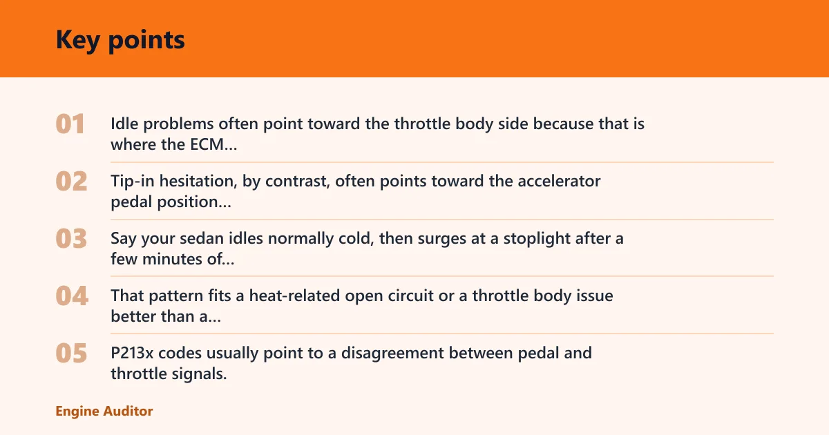
Idle problems often point toward the throttle body side because that is where the ECM controls air bypass and plate position most tightly. Tip-in hesitation, by contrast, often points toward the accelerator pedal position sensor or its wiring, especially if the symptom appears only during the first part of pedal travel.
Say your sedan idles normally cold, then surges at a stoplight after a few minutes of driving. That pattern fits a heat-related open circuit or a throttle body issue better than a simple dead pedal sensor, because the fault appears after underhood heat rises.
What correlation faults point
P213x codes usually point to a disagreement between pedal and throttle signals. That can mean the sensor is bad, but it can also mean a connector is corroded, a wire opens when hot, or the throttle body motor cannot reach the commanded position. Do not replace parts before checking the data path.
When the throttle body is the better suspect
If commanded throttle changes normally but actual throttle lags, sticks, or never reaches the target, the throttle body deserves attention first. Contamination on the bore or plate, a failing motor, or a TPS fault can all create that pattern. A P012x code family leans toward throttle-side diagnosis.
Which codes point to a bad sensor?
P012x codes usually involve the throttle position sensor or throttle body angle reporting. P213x codes usually involve pedal and throttle correlation. Pending codes matter too, because an intermittent fault may show up there before it turns into a steady warning light.
P012x family basics
P012x codes often point to a TPS signal that is implausible, out of range, or not moving as expected. On a potentiometer-type sensor, worn contacts can create dropouts. The same source notes that a faulty throttle valve potentiometer can cause engine jolts or splutters, poor acceleration, and increased fuel consumption.
P213x correlation faults
P213x codes often mean the ECM sees pedal and throttle data that do not agree. China-Runtong notes that dual-track TPS designs provide two independent output signals simultaneously, and the same logic applies to pedal redundancy. If the two tracks diverge too far, the system protects itself.
What to do with pending versus stored codes
Stored codes point to a fault the ECM has confirmed. Pending codes point to a fault it has seen but not fully confirmed yet. If the complaint is intermittent, pending codes and freeze-frame data can be more useful than a quick scan after the car has cooled off.
How do you check live data?
A scan tool is the fastest first check because it shows live data, commanded versus actual throttle, and stored codes. Look for APP1 and APP2, TPS values, commanded throttle angle, and actual throttle angle. You are looking for smooth movement, matching trends, and no sudden drops.
What to watch on a scan tool
Watch the numbers with the key on and engine off first. Then move the pedal slowly from closed to wide open. APP tracks should rise smoothly. TPS should follow throttle movement smoothly. If one track flat-lines, spikes, or lags behind, that trace deserves attention.
Picture a crossover that enters reduced power only during light acceleration onto a ramp. A scan tool may show APP tracks rising normally, while actual throttle angle pauses for a second. That pattern points more toward throttle body control or wiring than a simple pedal sensor failure.
Commanded versus actual throttle
Commanded throttle is what the ECM asks for. Actual throttle is what the sensor reports. If commanded and actual stay close, the throttle body is probably doing its job. If they separate, the fault may be the throttle motor, the TPS, or a wire problem between the parts.
Pedal sweep and signal mismatch
During a slow pedal sweep, both APP tracks should move without dead spots. A mismatch greater than about 10% between redundant tracks is a warning sign. That kind of disagreement is one of the clearest reasons the system enters fault detection and limits throttle response.
What simple tests can you do next?
Start with the easy checks. Inspect connectors, wiring, and contamination before replacing parts. Resistance testing applies mainly to potentiometer-style sensors, and it should show smooth change as the throttle opens. If the fault is intermittent, heat and vibration can matter as much as the sensor itself.
Connector and wiring inspection
Unplugged terminals, bent pins, corrosion, and broken wire strands can mimic a bad sensor. Check the connector at the pedal and the throttle body. Look for chafing where the wiring bends, especially near the firewall, intake ducting, or pedal bracket.
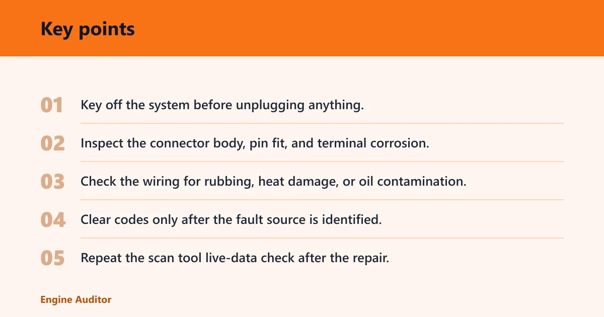
- Key off the system before unplugging anything.
- Inspect the connector body, pin fit, and terminal corrosion.
- Check the wiring for rubbing, heat damage, or oil contamination.
- Clear codes only after the fault source is identified.
- Repeat the scan tool live-data check after the repair.
Resistance testing on potentiometer types
For potentiometer-style TPS units, use an ohmmeter with the throttle valve closed and then move it slowly open. The reading should change smoothly without dropouts. The same source recommends checking resistance in that way. An interruption suggests worn contacts or internal damage.
For cable checks, HELLA gives an approximate continuity reference value of 0 ohms, and a short-to-ground reference value of approximately greater than 30 MOhm. Those figures help separate a broken path from a grounded fault in the wiring.
When contamination or calibration is the issue
Contamination inside the throttle body can make the plate stick or return inconsistently. That can look like a sensor fault on a scan tool. Some systems also need a relearn or calibration after cleaning or replacement, so a correct part can still act wrong until the ECM relearns its range.
When does limp mode point to sensor trouble?
Reduced-power limp mode often appears when the ECM sees disagreement between pedal and throttle signals. It is a failsafe, not a diagnosis. The system limits throttle response to prevent uncontrolled opening, so the fix still depends on whether the problem is sensor, wiring, throttle body, or calibration.
Reduced-power warnings
A reduced-power warning with poor throttle response is a strong clue that the ETC system has detected a fault path. That warning often comes with correlation codes or implausible signal codes. It does not automatically mean the pedal sensor is bad, but it does mean the system has rejected one of its inputs.
Failsafe behavior from signal disagreement
When APP and TPS disagree, the ECM may ignore part of the pedal request. That is why the engine can idle but refuse to accelerate normally. In hybrids and EVs, the same logic may limit torque request rather than throttle plate angle, but the diagnosis still starts with the input signals.
Why the system limits throttle response
The point of ETC safety logic is simple: if the system cannot trust the signals, it reduces the chance of an unintended surge. That is why a bad connector, a worn track, or a sticking throttle body can all create the same reduced-power result.
Frequently asked questions
How to tell if a throttle position sensor is bad
A bad TPS usually shows an erratic live-data trace, an implausible closed-throttle value, or a mismatch between commanded and actual throttle angle. P012x codes are the usual clue. If the sensor is potentiometer type, an ohmmeter test may show dropouts as the throttle opens.
How to check if a throttle position sensor is bad
Check codes first, then watch live TPS data while moving the throttle slowly. The signal should rise smoothly without jumps or flat spots. If the vehicle has a potentiometer-style sensor, resistance should change smoothly. Corrosion, worn contacts, or a bad ground can create the same symptoms.
How to tell if a throttle position sensor is going bad
A TPS that is going bad often fails intermittently before it fails fully. Watch for a brief hesitation, a momentary surge, or a code that returns only after heat soak. Intermittent faults often point to contact wear, connector corrosion, or an internal open that appears only when warm.
What are the symptoms of a bad accelerator pedal sensor?
Common symptoms include hesitation, a dead spot during tip-in, no response from the pedal, and reduced-power behavior. Because the pedal sensor measures driver request, the problem may show up most clearly during the first part of pedal travel. A scan tool can confirm whether APP tracks move smoothly.
Will a bad throttle position sensor cause stalling?
Yes, a bad TPS can cause stalling, especially if it reports the wrong closed-throttle angle or drops out as the throttle returns to idle. That can confuse the ECM’s air and fuel control. Stalling at idle, or just after lifting off the pedal, is a common clue.
How to tell if gas pedal sensor is bad
Watch APP1 and APP2 on a scan tool while pressing the pedal slowly. If one track stays flat, jumps, or disagrees with the other, the pedal sensor is suspect. If both tracks stay smooth but the throttle does not respond, check the throttle body, wiring, or ETC control.
Products related to this article
Sponsored / affiliate links. As an Amazon Associate I earn from qualifying purchases. I may earn additional commission from eligible campaigns.