
How Do I Test a Radiator Fan Relay?
Test a radiator fan relay by checking battery power at the feed, a switched ground or control signal at the coil, and continuity across the load contacts; if the relay clicks but the fan still fails, move to the fuse, motor, wiring, or command signal. Missed diagnosis can mean wasted parts, repeat overheating, and an A/C system that stays weak at idle. This guide gives you a fault-isolation sequence so you can prove whether the relay, fan motor, fuse, sensor, or wiring is at fault before you replace anything.
Radiator fan relay basics


The radiator fan relay is an electrical switch that lets a low-current control signal turn a high-current fan circuit on and off. Electric radiator cooling fans use a relay to switch high current on and off, so the relay sits between the control side and the fan motor feed.
On many vehicles, the relay is near the engine-compartment fuse box or mounted low on a metal frame near the bottom of the engine compartment. Heat, corrosion, loose terminals, and water intrusion can weaken the coil or burn the contacts. A bad relay can look exactly like a failed fan motor or a wiring problem.
Why the relay matters in the cooling circuit
If the relay does not close, the fan never gets battery power. If the contacts are burned, the relay may click but pass little or no current to the motor. That is why a click alone is not proof of a good relay.
OEM service information typically treats the relay as part of a system test, not an isolated part test: confirm the fuse feed, verify control command, and then verify output to the motor. On Bosch-style relays, terminal numbers are commonly 30 for battery feed, 85 and 86 for the coil, 87 for switched output, and 87a for the normally closed contact; always verify the actual pinout on the relay case or wiring diagram before testing.
Some vehicles use a separate fan control module instead of a simple plug-in relay. On those systems, a relay-style swap test may not apply, so vehicle-specific wiring data matters before you start pulling parts.
What symptoms point to a bad fan relay?
A bad fan relay often shows up as a fan that never comes on at idle, slow traffic, or when the A/C is commanded on. It can also cause intermittent fan operation, weak A/C cooling at low speed, or overheating that improves once the car is moving faster.
Those symptoms do not prove the relay is bad. They only tell you the fan circuit is not doing its job, which means the fuse, relay, motor, wiring, coolant temperature input, or control module still needs to be separated by test.
No fan at idle or in traffic
If the fan works on the highway but not in traffic, the issue may be control logic, sensor input, the relay coil, or a bad socket connection. The fan often gets its strongest command when the engine is hot and vehicle speed is low.
A/C performance drops at low speed
Many vehicles request fan operation when the A/C is on MAX and the engine is running. That is a practical no-meter check because the A/C request should trigger the fan on many systems when the PCM sees the proper conditions. If the fan does not run in that condition, the fan circuit needs deeper diagnosis.
Intermittent fan operation
Intermittent operation points to heat-related relay failure, corroded terminals, or a wiring open that comes and goes with vibration. A relay may work cold, then fail after heat soak.
Locate the fuse and relay first
Start with the owner’s manual or repair manual. It identifies the exact fuse and relay location, which matters because layout varies by vehicle. Check the high-amperage fan fuse first, then move to the relay; use the rating shown in the vehicle’s service information rather than assuming a generic value.
If the fuse is blown, replace it only after checking for a shorted motor or wiring fault. A new fuse that blows immediately means the problem is still present downstream.
How to identify the correct socket
Do not assume every relay in the box is the fan relay. Labeling is often close, but not always clear. The manual, wiring diagram, or cover legend is the only reliable guide to the correct relay socket.
- Switch the ignition off and let hot parts cool enough to handle safely.
- Open the underhood fuse/relay box and identify the fan fuse and fan relay from the manual.
- Inspect the fuse first.
- Check the relay socket for heat damage, corrosion, or loose terminals.
- Only then move to electrical testing.
Fan relay decision table
| Symptom | Test | Expected reading or result | Likely fault if it fails |
|---|---|---|---|
| No fan with A/C on MAX | No-multimeter check: engine running, A/C on MAX, listen for relay click and fan operation | Relay clicks and fan runs within a short time | Relay, fuse, motor, wiring, or command signal |
| No fan at idle | Multimeter check: verify power at the fan connector | Battery voltage present at the fan connector | No voltage at the fan connector means power is not reaching the fan; suspect fuse, relay, wiring, or control side |
| Relay clicks but fan stays off | Multimeter check: test continuity across relay load contacts | Low resistance when energized; open circuit when de-energized | Burned relay contacts or wiring open |
| Fan runs with direct power | Multimeter or jumper-wire test: apply direct battery power to the motor | Fan spins strongly and steadily | Relay, fuse, wiring, sensor, or control module rather than the motor |
| Fan will not run with direct power | Direct power test at the fan motor | No movement or weak movement | Fan motor fault or poor motor ground |
| Intermittent fan operation | Inspect socket and harness for corrosion, heat damage, or loose terminals | Clean, tight terminals with no discoloration or melting | Wiring or socket fault that imitates relay failure |
| Fan comes on late or not at all when hot | Check coolant temperature sensor signal path | Sensor input changes with engine temperature | Faulty coolant temperature sensor or control input |
| Vehicle uses a control module | Verify module command and outputs with vehicle-specific data | Command and output match the scan or wiring diagram | Fan control module or solid-state relay fault |
How do you test a radiator fan relay with a multimeter?
Use the multimeter to check the coil, the switched contacts, and power at the relay socket. Set the meter to ohms for the relay coil, and use voltage-drop or continuity checks on the load side. A failed relay can be confirmed if either the coil or contacts fail the test. That gives you a pass/fail result instead of a guess.
Test coil resistance
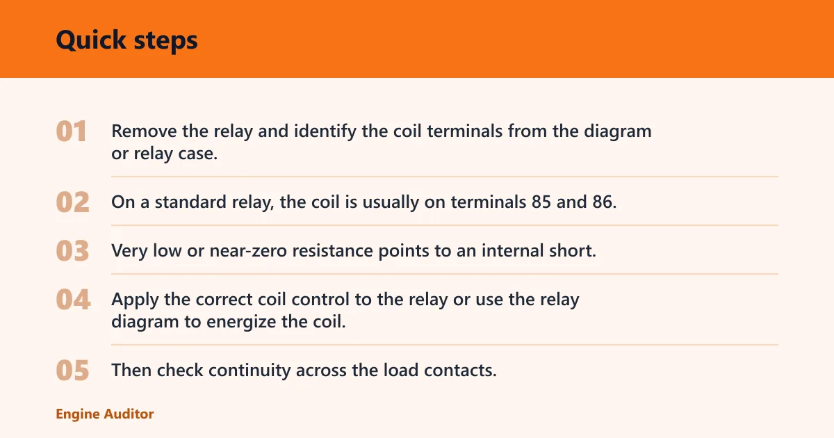
Remove the relay and identify the coil terminals from the diagram or relay case. On a standard relay, the coil is usually on terminals 85 and 86, but verify the pinout first. Measure resistance across the coil pins. An open circuit means the coil is broken. Very low or near-zero resistance points to an internal short. Either result is a failed relay.
Check switched continuity
Apply the correct coil control to the relay or use the relay diagram to energize the coil. Then check continuity across the load contacts. A good relay should close cleanly and show low resistance across the switched path when energized, then open again when power is removed. In practical terms, “open” means no continuity and very high resistance; “low resistance” means a near-continuous path that allows current to flow with minimal drop.
Verify power in and power out at the socket
At the relay socket, check for battery voltage at the feed terminal. Battery voltage with the engine off is usually around 12.6 volts on a fully charged battery and commonly in the 12.4 to 12.8-volt range; with the engine running, charging voltage is typically higher. Then command the fan on and check the output terminal. If power enters the relay socket but never leaves, the relay or its control signal is the problem. If there is no feed power, the fault is upstream in the fuse or wiring.
If the relay clicks but the fan still does not run, measure voltage at the fan connector while the circuit is commanded on. A relay can click and still fail under load if the contacts are burned or the socket terminals are loose. In that case, a voltage reading that sags significantly under load points to a high-resistance connection even though the relay audibly operates.
Picture a fan that never comes on during a traffic jam, but the A/C still blows cold at speed. If the relay socket has battery power and the coil command is present, yet the output stays dead, the relay is the likely failure. If the output is present but the fan still does nothing, the motor or ground path is more likely.
How can you test a fan relay without a multimeter?
Without a multimeter, use a known good relay swap, the A/C command test, and a careful listen for relay click and fan response. This will not prove every fault, but it can separate a dead relay from a working one when basic tools are all you have.
Swap with a known good relay
Swap the fan relay with another relay of the same part number and pin layout. If the fan starts working and the swapped-in circuit still operates, the original relay is suspect. Do not swap relays that are unlike or have different amperage ratings.
Use the A/C command to request fan operation
With the engine running and the A/C on MAX, many vehicles should request fan operation. If the fan comes on during the A/C request, the relay and motor are at least capable of operating under command.
Listen for relay click and fan response
A relay click means the coil is likely being commanded, but the contacts still may be burned. No click points to a control-side problem, a bad coil, or no command signal. If there is a click but no fan movement, move to the fuse, motor, or wiring check.
A common shop pattern is a relay that clicks every time, yet the fan only spins after the relay is tapped or the connector is reseated. That usually points to heat-damaged contacts or spread terminals, not a dead coil. Another frequent pattern is a relay that tests fine on the bench but fails in the vehicle because the socket terminal is loose or corroded and drops voltage under load.
Check the fan motor, wiring, and sensor input
If the relay passes or the test result is unclear, prove the fan motor and circuit path next. OEM-style diagnostics usually separate the load side from the control side before condemning the relay. A direct-power test is one of the quickest ways to separate a bad motor from an upstream fault, but it should be done carefully and with fused jumper leads.
Apply direct 12V to the fan motor
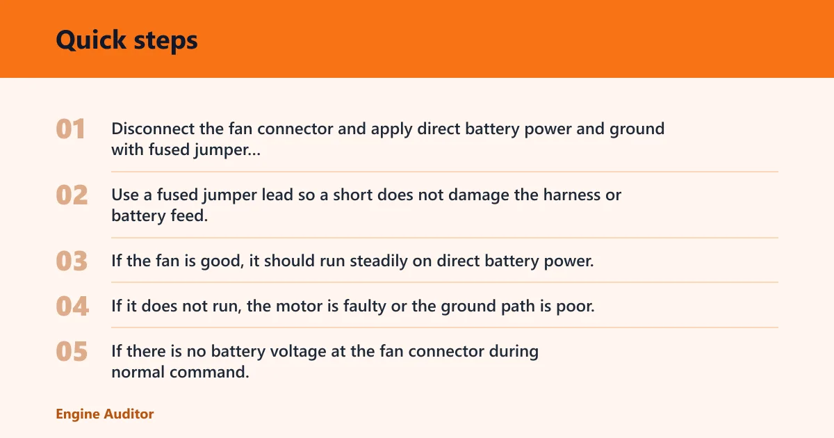
Disconnect the fan connector and apply direct battery power and ground with fused jumper wires, following polarity and safety precautions. Use a fused jumper lead so a short does not damage the harness or battery feed. If the fan is good, it should run steadily on direct battery power. If it does not run, the motor is faulty or the ground path is poor.
If there is no battery voltage at the fan connector during normal command, power is not reaching the fan. That means the issue is upstream, not in the fan motor itself.
Inspect the relay socket and wiring harness
Look for green corrosion, heat damage, melted plastic, spread terminals, and broken insulation. A loose or oxidized socket can act like a bad relay. Wiggle testing the harness lightly while monitoring fan operation can reveal an open circuit that comes and goes.
Check the coolant temperature sensor signal path
The coolant temperature sensor tells the control side when the engine is hot enough to request fan operation. In many systems, the PCM uses that input along with A/C pressure and vehicle speed to decide when to ground or power the relay coil. If the sensor reads cold all the time, the fan may never be commanded on. Use the service manual for the expected sensor strategy instead of relying on a universal temperature number.
That is why a relay can look bad even when the real fault is a sensor, wiring open, or fan control module. A bad input signal stops the relay from being commanded in the first place.
When the problem is not the relay
Some vehicles use a fan control module or a solid-state relay instead of a simple plug-in relay. If the relay socket does not match the expected Bosch-style terminal pattern, or the module is pulse-width controlled, a standard swap test may miss the real fault. In that case, you need vehicle-specific wiring and command data.
If the fan motor runs on direct power, the fuse is good, and the relay has correct feed and command signals but still does not pass current, the relay is a strong suspect. If the relay looks good but the control side never commands it, look at the coolant temperature sensor, A/C request input, module output, or wiring.
How to tell whether the control side switches ground or power
Check the diagram before probing the coil. Some systems switch the ground side of the relay coil, while others switch battery power. If the control side is ground-switched, one coil terminal will have battery voltage and the PCM or module completes the circuit by providing ground. If the system is power-switched, the control side supplies voltage instead. Verify the expected behavior with the wiring diagram so you do not misread a good circuit as a failure.
When to stop and use vehicle-specific data
Stop and consult the repair manual when the relay location is unclear, the connector pinout does not match the diagram, or the vehicle uses multiple fan speeds or module control. Those systems can use logic that a generic relay test will not capture.
How do I know if my radiator fan relay is bad?
You know a radiator fan relay is bad when it fails a coil resistance test, fails switched continuity, or loses power output at the socket even though the feed and command are present. A relay that clicks but does not pass current is also suspect, but only after the fuse, motor, and wiring checks are done.
Frequently asked questions
How do I test a cooling fan relay?
Check the fan fuse first, then test the relay coil and contacts with a multimeter or swap in a known good relay. If the relay receives power and command but does not send power out, the relay is likely bad. If it passes, move to the motor, wiring, or sensor.
How do you test a radiator fan relay?
Use the manual to find the exact relay, then verify power at the socket, continuity across the contacts, and coil resistance. A good relay should click and close the load circuit when commanded. If the relay tests good, the fault is likely elsewhere in the cooling fan circuit.
How to test a radiator fan relay with a multimeter
Set the meter to ohms for coil testing, then check continuity across the switched contacts when the coil is energized. Also verify battery voltage at the feed terminal and voltage at the output terminal during command. Pass/fail readings tell you whether the relay is switching current correctly.
Related guides
- Cooling fan not working
- Coolant temperature sensor testing
- Fan motor testing
- Blown fuse diagnosis
- Overheating at idle
Sources
OEM service manual procedures for cooling fan relay and circuit testing; relay terminal identification standards commonly used on Bosch-style relays; manufacturer wiring diagrams and diagnostic flowcharts for fan control, fuse, relay, motor, and coolant temperature input checks.
Products related to this article
Sponsored / affiliate links. As an Amazon Associate I earn from qualifying purchases. I may earn additional commission from eligible campaigns.