How to Read a Car Wiring Diagram as a Beginner
Read a car wiring diagram by tracing one circuit from power source to load to ground, then confirm the hot side has voltage and the ground side has continuity. If you read it poorly, you can chase the wrong wire, replace the wrong part, and waste hours. This guide walks through symbols, wire colors, connectors, grounds, fuses, and one full circuit test path.
What a wiring diagram actually shows


An automotive wiring diagram shows circuit flow, not the physical route of the wiring. The page tells you where power starts, where it is protected, how it is switched, what the load is, and how current returns to ground. It may be grouped by system, circuit, or page section, so the same vehicle can have several diagram styles across the manual.
That is why a diagram can look nothing like the car. A wire drawn near a fuse box on the page may run across the body in real life, or pass through a connector and a splice before it reaches a module. Year, engine, trim, and option package can change the circuit, so a factory source or service manual for the exact vehicle matters.
How to start with the right source
Use a year, make, model, engine, and trim-specific service manual or factory wiring diagram source first. Random internet images often mix years or leave out circuit revisions, connector views, or splice locations. If the manual has a legend, connector face views, and circuit index, start there before reading any symbol on the page.
- Confirm the exact model year and engine.
- Open the diagram legend or key.
- Find the circuit by system name or circuit number.
- Note connector IDs, pin numbers, wire colors, and splice IDs.
- Trace the circuit from source to load to ground.
How do you start with the legend?
Start with the legend or key before you interpret any symbol or abbreviation. The same icon can mean different things across publishers, and service manuals often use short labels that make sense only after you check the key. If the manual says a symbol is a splice, connector, or ground, trust that key first.
Most beginner mistakes begin here. A circle with a letter inside may mark a connector on one manual and a test point on another. A short code beside a line may identify a wire color, a cavity number, or a splice ID. The legend tells you which is which.
Symbols and abbreviations to identify first
Look first for battery power, fuse, relay, switch, load, connector, splice, and ground. Battery is the source of B+ power. A fuse protects the circuit. A relay switches current with a low-current control side and a higher-current load side. The load may be a motor, sensor, lamp, horn, or module.
Also watch for abbreviations that show circuit state. “B+” usually means battery voltage. “IGN” often means ignition-switched power. “GND” or a ground symbol marks return to chassis or signal ground. Connector IDs, such as C101 or A12, and pin labels, such as cavity 4 or terminal B, can help match the page to the plug in the vehicle.
How to spot wire color codes and tracer stripes
Wire colors are often written as a base color plus tracer stripe, such as BLK/WHT for black with white tracer or RED/BLU for red with blue tracer. That helps identify a circuit path through the wiring. Do not assume a wire color is universal; manufacturers can change codes by model year, market, or option package.
Some diagrams use full color words, others use abbreviations, and some show only the main color without the stripe if the stripe is not present. If the wire color in the page does not match the wire in the car, stop and recheck the manual edition, connector view, and circuit number before moving on.
Where connector pin numbers and splice IDs appear
Connector pin numbers tell you which terminal in a plug to probe. They may be printed as cavity numbers, terminal IDs, or pin positions. Splice IDs identify a branch point where one wire feeds two or more paths, which matters when a circuit dies at one branch but still works at another.
Many beginners trace only the main line and miss the branch. If the diagram shows a splice labeled S203, that point may split power to more than one load. Check the splice before assuming the wire is open. Connector face views are especially useful when a plug has many terminals packed into a small shell.
How do power and ground show up on the page?
Power and ground are the two ends of the troubleshooting map. Start on the hot side when a circuit is dead, then verify the return path on the ground side. Battery feed, ignition feed, and switched power are not the same thing, and a diagram usually shows which one the circuit needs at each stage.
A ground symbol can mark chassis ground, signal ground, splice ground, or a module ground point. That detail matters during voltage-drop diagnosis, because a ground can look fine on paper and still fail under load. The page should tell you where the circuit returns and whether the ground point is shared.
Battery feed, ignition feed, and switched power
Battery feed is always hot unless the circuit is protected or opened upstream. Ignition feed becomes hot only when the ignition switch is in the correct position. Switched power may come from a relay, module, or switch. The diagram should show which state the circuit needs before you probe anything.
If a horn works with key off, it may have direct battery feed. If a blower or fuel pump only works in key-on or crank, the diagram may show ignition-switched power or relay control. That difference changes where you start the test.
Fuse and relay paths, including control side and load side
Fuses usually sit upstream of the load and protect the circuit from overcurrent. Relays split into a control side and a load side. The control side is the coil that the switch or module energizes. The load side is the contact path that actually sends power to the load.
When the circuit uses a relay, do not test only one side. A relay can click and still fail on the load contacts, or it can have power at the fuse but no output to the load. The diagram will often show the coil pins separately from the switched contact pins.
Ground symbols, splice grounds, and module grounds
Ground symbols point to the return path for current. A direct ground may go to the body, frame, or engine block. A splice ground bundles several wires to one ground point. Module grounds may be signal grounds that must stay clean and low resistance for sensor accuracy.
For a ground-side diagnosis, place the meter on the load side and check whether the circuit can complete to ground. A high resistance ground can let a multimeter show continuity while the circuit still fails under load, so a voltage-drop check is often more useful than a simple beep test.
How do you trace one circuit from source to load?
Trace one circuit in order: source, protection, control, load, and ground. Read the page from the battery or ignition feed toward the device, then back through the return path. Use the connector pin numbers to match the drawing to the physical plug, and stop at each splice or branch point instead of skipping ahead.
A common beginner mistake is assuming a windshield washer pump is dead before tracing the fuse, switch, and ground in the wiring diagram. Suppose the diagram shows battery feed into a horn relay, then a steering wheel switch that grounds the relay coil. If the relay coil gets ground but the load side has no output, the fault is in the relay or upstream feed, not the horn itself.
Follow the circuit in order
Read the path line by line. First confirm source power at the battery or ignition feed. Then check the fuse. Next check the relay or switch that controls current. After that, find the load. Finally, verify the ground path back to chassis or module ground.
If the circuit branches, note each split. A branch may feed several lamps, sensors, or modules from one splice. Do not assume the first branch is the only path. The diagram may show a shared fuse feeding multiple loads, which can make one bad branch easy to miss.
Use pin numbers to match the drawing to the connector
Pin numbers matter because the diagram often tells you exactly which cavity to probe. If the manual says connector C204, cavity 7, you need the pin location on the connector face, not the color of the shell or the order of the wires. Terminal IDs can be different from cavity numbers, so read both if the manual provides both.
That detail helps when a module connector has 20 or more pins. The wire may be easy to see, but the cavity may be hidden by the housing shape or locking tab. The face view in the service manual prevents a lot of guesswork.
Check branch points and splices before assuming a wire break
Splice points are common failure checks because one feed can split to several loads. If one branch works and another does not, the break may be between the splice and the failed load, not at the source. Check continuity from the splice to the load only after confirming power reaches the splice itself.
Picture a headlight circuit where the left lamp works and the right lamp does not. If both lamps share the same fuse and relay but separate branch wires after a splice, the issue may be on the right branch after that split. The diagram tells you where that split begins.
Car wiring diagram as table
The horn circuit is a good first walkthrough because it usually includes battery feed, fuse protection, a relay, a switch or module command, a load, and ground. The table below shows how to read the diagram as a test plan, not as a drawing of where the wires sit in the car.
| Symbol | What it means | Where to probe | Expected voltage or continuity | Common beginner mistakes |
|---|---|---|---|---|
| Battery / B+ | Direct power source from the battery | Fuse input or relay feed terminal | About 12.4 to 12.8 volts with engine off on a charged 12-volt system | Testing only the battery posts and skipping the fuse input |
| Fuse | Overcurrent protection for the circuit | Both sides of the fuse with meter leads | Battery voltage on both sides if the fuse is good and the circuit is live | Assuming a fuse is good by sight alone |
| Relay | Switching device with control side and load side | Coil pins for command, contact pins for output | Control side should see command voltage or ground; load side should pass battery voltage when energized | Checking only for a click and assuming the contacts work |
| Switch | Driver input or module command path | Switch terminals or steering wheel switch circuit | Continuity or ground path when activated, depending on design | Assuming every switch sends power; many switch grounds instead |
| Load | The device being powered, such as the horn | Load connector pin and case or ground terminal | Battery voltage at the power pin during command, good ground at the return side | Replacing the load before verifying feed and ground |
| Ground symbol | Return path to chassis or module ground | Ground pin, ground splice, or body ground point | Low resistance continuity, and low voltage drop under load | Using only the beep test and ignoring voltage drop |
Which tools should you use on the circuit?
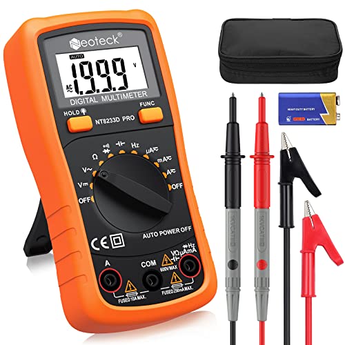
A multimeter is the main tool for reading the circuit in real time. Set it to DC volts for power checks, continuity for simple path checks, and resistance only when the circuit is powered down. A test light can be useful on higher-current circuits, but it is not the right choice for every module-controlled circuit.
Disconnect power when needed, especially before checking resistance or continuity on sensitive circuits. Avoid shorting terminals with meter probes, and back-probe carefully if the connector design allows it. If a circuit controls a module, sensor, or airbag-related component, follow the manual before applying a test light or jumper.
Multimeter settings for voltage, continuity, and resistance
Use DC volts to confirm power at the fuse, relay, switch, and load. Use continuity to check whether a wire path is open or closed with the circuit de-energized. Use resistance only when the manual calls for it, because a low-ohms reading alone does not prove the circuit will carry current under load.
A good habit is to measure at both ends of the section you suspect. If voltage is present at the fuse input but absent at the relay output, the fault lies between those points or inside the relay. If continuity exists on a ground wire but the circuit still fails, check for voltage drop on the ground side.
When a test light is useful
A test light is handy for quick power checks on many higher-current circuits such as lamps, horns, or some relays. It can load the circuit slightly, which sometimes reveals a weak connection that a high-impedance meter may miss. Use it only where the manual and circuit type make it appropriate.
Do not use a test light on every module circuit. Sensitive control lines can be damaged or falsely loaded by the wrong tool. If the diagram shows a low-current signal, a sensor reference, or a module data path, stay with the multimeter and the factory procedure.
Why the wrong tool can hide a fault
A meter can show voltage through a weak connection that collapses under load. A test light can make a marginal circuit fail harder than it would in normal use. That is why the diagram and the tool must match the test goal: power-side checks, ground-side checks, or signal verification.
For example, if a horn relay has 12 volts at the feed but the horn only chirps weakly, a voltage-drop test on the ground side may show excessive resistance at the body ground point. A continuity beep alone may miss that problem.
Frequently asked questions
What is the difference between a wiring diagram and a schematic?
In car repair use, the terms often overlap, but a wiring diagram usually helps you follow vehicle-specific circuit flow and connector locations, while a schematic focuses more on logical circuit operation. For diagnosis, the factory wiring diagram is usually the better source because it includes pin numbers, splice IDs, and color codes.
How do I trace power and ground on a car wiring diagram?
Trace power from battery or ignition feed through the fuse and relay to the load, then trace the return path through the ground symbol back to chassis or module ground. Test the hot side for voltage first, then test the ground side for continuity and voltage drop under load.
How can I tell which wire is hot, ground, or switched power?
The diagram usually labels battery power as B+, ignition power as IGN, and ground with a ground symbol or GND notation. Switched power often appears after a relay or switch. Confirm with the key position and a meter, because wire color alone does not prove function.
How do connector pin numbers work on automotive diagrams?
Connector pin numbers identify the exact cavity or terminal in a plug. The diagram may list them as cavity numbers or terminal IDs, and the manual often provides a connector face view. Match that view to the physical plug so you probe the correct wire, not just the correct connector shell.
Where do I find the correct wiring diagram for my car?
Use a factory service manual or a year, make, model, engine, and trim-specific wiring source. Those sources usually include diagram revisions, connector views, and system-specific pages. Avoid generic internet images unless they match the exact vehicle and can be checked against the factory legend and circuit index.
Products related to this article
Sponsored / affiliate links. As an Amazon Associate I earn from qualifying purchases. I may earn additional commission from eligible campaigns.